Introduction to programmable logic controllers (PLCs) and the operational function of main system modules
This tutorial offers an in-depth introduction into programmable logic controllers (PLCs). The article starts with an overview of the history and the role PLCs in factory automation. The basic principles of PLC operation are discussed. The core modules of an industrial-control system are examined: the analog input function, analog output functions, the distributed control (fieldbus) interface, digital inputs and outputs (I/Os), the CPU, and isolated power. Functional block diagrams and recommended devices are included for each function.
Overview
Programmable logic controllers (PLCs) have been an integral part of factory automation and industrial process control for decades. PLCs control a wide array of applications from simple lighting functions to environmental systems to chemical processing plants. These systems perform many functions, providing a variety of analog and digital input and output interfaces; signal processing; data conversion; and various communication protocols. All of the PLC's components and functions are centered around the controller, which is programmed for a specific task.
The basic PLC module must be sufficiently flexible and configurable to meet the diverse needs of different factories and applications. Input stimuli (either analog or digital) are received from machines, sensors, or process events in the form of voltage or current. The PLC must accurately interpret and convert the stimulus for the CPU which, in turn, defines a set of instructions to the output systems that control actuators on the factory floor or in another industrial environment.
Modern PLCs were introduced in the 1960s, and for decades the general function and signal-path flow changed little. However, twenty-first-century process control is placing new and tougher demands on a PLC: higher performance, smaller form factor, and greater functional flexibility. There must be built-in protection against the potentially damaging electrostatic discharge (ESD), electromagnetic interference and radio frequency interference (RFI/EMI), and high-amplitude transient pulses found in the harsh industrial setting.
Robust design
PLCs are expected to work flawlessly for years in industrial environments that are hazardous to the very microelectronic components that give modern PLCs their excellent flexibility and precision. No mixed-signal IC company understands this better than Maxim. Since our inception, we have led the industry with exceptional product reliability and innovative approaches to protect high-performance electronics from real environmental dangers, including high levels of ESD, large transient voltage swings, and EMI/RFI. Designers have long endorsed Maxim's products because they solve difficult analog and mixed-signal design problems and continue solving those problems year after year.
Higher integration
PLCs have from four to hundreds of input/output (I/O) channels in a wide variety of form factors, so size and power can be as important as system accuracy and reliability. Maxim leads the industry in integrating the right features into ICs, thereby reducing the overall system footprint and power demands and making designs more compact. Maxim has hundreds of low-power, high-precision IC's in the smallest available footprints, so the system designer can create precision products that meet strict space and power requirements.
Factory automation, a short history
Assembly lines are a relatively new invention in human history. There have likely been many parallel inventions in many countries, but here we will mention just a few highlights from the U.S.
Samuel Colt, the U.S. gun manufacturer, demonstrated interchangeable parts in the mid-1800s. Previously each gun was assembled with individually made pieces that were filed to fit. To automate that assembly process, Mr. Colt placed all the pieces for ten guns in separate bins and then assembled a gun by randomly pulling pieces from the bins. Early in the twentieth century Henry Ford expanded mass-production techniques. He designed fixed-assembly stations with cars moving between positions. Each employee learned just a few assembly tasks and performed those tasks for days on end. In 1954 George Devol applied for U.S. Patent 2,988,237, which enabled the first industrial robot named Unimate. By the late 1960s General Motors? used a PLC to assemble automobile automatic transmissions. Dick Morley, known as the "father" of the PLC, was involved with the production of the first PLC for GM?, the Modicon. Morley's U.S. Patent 3,761,893 is the basis of many PLCs today. (For more information on the above four inventors, please see: www.wikipedia.org/; for their patents, search: http://patft.uspto.gov/netahtml/PTO/srchnum.htm).
Basic PLC operation
How simple can process control be? Consider a common household space heater.
The heater's components are enclosed inside one container, which makes system communications easy. Expanding on this concept is a household forced-air heater with a remote thermostat. Here the communication paths are just a few meters and a voltage control is typically utilized.
Think now beyond a small, relatively simple process-control system. What controls and configuration are necessary in a factory?
The resistance of long wires, EMI, and RFI make voltage-mode control impractical. Instead, a current loop is a simple, but elegant solution. In this design wire resistance is removed from the equation because Kirchhoff's law tells us that the current anywhere in the loop is equal to all other points in the loop. Because the loop impedance and bandwidth are low (a few hundred ohms and < 100Hz), EMI and RFI spurious pickup issues are minimized. A PLC system is useful for properly controlling such a factory system.
A household electric heater serves as a simple example of process control.
Longer-range factory communications.
Current communication for PLCs
Current-control loops evolved from early twentieth-century teletype impact printers, first as 0–60mA loops and later as 0–20mA loops. Advances in PLC systems added 4–20mA loops.
A 4–20mA loop has several advantages. Older discrete component designs required careful design calculations; circuitry was comparatively large compared to today's integrated 4–20mA ICs. Maxim has introduced several 20mA devices, including the MAX15500 and MAX5661, which greatly simplify the design of a 4–20mA PLC system.
Any measured current-flow level indicates some information. In practice, the 4–20mA current loops operate from a 0mA to 24mA current range. However, the electrical current ranges from 0mA to 4mA and 20mA to 24mA are used for diagnostics and system calibration. Since current levels below 4mA and above 20mA are used for diagnostics, one might conclude that readings between 0mA and 4mA could indicate a broken wire in the system. Similarly, a current level between 20mA and 24mA could indicate a potential short circuit in the system.
An enhancement for 4–20mA communications is the highway-addressable remote transducer (HART? system) which is backward compatible with 4–20mA instrumentation. A HART system allows two-way communications with smart, microprocessor-based, intelligent field devices. The HART protocol allows additional digital information to be carried on the same pair of wires with the 4–20mA analog current signal for process-control applications.
PLCs can be described by separating them into several functional groups. Many PLC manufacturers will organize these functions into individual modules; the exact content of each of these modules will likely be as diverse as are the applications. Many modules have multiple functions that can interface with multiple sensor interfaces. Yet other modules or expansion modules are often dedicated to a specific application such as a resistance temperature detector (RTD), sensor, or thermocouple sensor. In general, all modules have the same core functions: analog input, analog output, distributed control (e.g., a fieldbus), interface, digital input and outputs (I/Os), CPU, and power. We will examine each of these core functions in turn, and leave sensors and sensor interfaces for a separate section.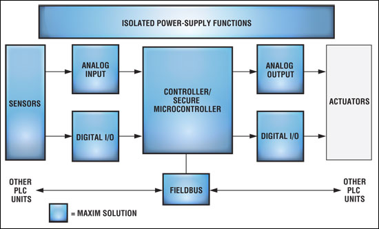
Simplified PLC block diagram.?
 電子發燒友App





評論