Introduction
Test and adjustment is used everywhere to assure IC quality. Electronics can speed test and make adjustment easy.The above statements tell a story in quite simple terms. Calibration makes products accurate, safe, and affordable. It allows manufacturers to deliver optimal devices at competitive prices. Maxim's large variety of digital calibration parts enables quick automated test and adjustment.
Electronic calibration can reduce cost in many areas. Calibration offers manufacturing, and the parent company, several distinct advantages. It helps ensure that parts meet manufacturing tolerances. A company can thus specify less-expensive components, reduce test time, improve reliability, and lower warrantee costs. With all this comes increased customer satisfaction, fewer customer returns, and faster product delivery.
Digitally controlled calibration devices and potentiometers (pots, DPots, and CDPots) are replacing mechanical pots in many products. The advantages are reduced test time and expense because human error is removed. Digital calibration devices are insensitive to vibration, dust, dirt, and moisture, which can cause failure in mechanical pots. This increased reliability can reduce product liability concerns and improve product safety. In addition, the small size of electronic calibration devices benefits small board layouts and portable devices.
Calibration circuit FAQs
What is a calibration device?
A calibration device is an adjustable part with a predictable power-on-reset (POR) condition. Usually POR will read a value stored in nonvolatile (NV) memory in the device. Alternative devices that POR to zero, midscale, or full-scale can also be used in selected circuits.How does a digital pot work?
A digital potentiometer is a solid-state device consisting of a string of resistors and a series of switches (Figure 1). It emulates a mechanical potentiometer, and only one wiper switch is on at a given time. Digital pots are controlled with an SPI?, I2C, or up/down digital interface.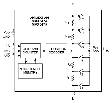
Figure 1. The MAX5474/MAX5475 NV digital pots have ultra-low temperature drift.
Figure 2 shows the internal construction of a typical analog switch featuring parallel n- and p-channel MOSFETs and the on-resistance of the pair (Figure 3). DPots typically operate at lower voltage compared to the switch, but this illustrates the concept. Figure 4 is the simplified typical electrostatic discharge (ESD) structure that protects the integrated circuits (ICs). The wiper capacitance is that of the single on-switch in parallel with all the capacitance of off-switches. In Figure 4, part C is typical of the circuits attached to all three pot signal pins. This means that the voltage on the pot needs to be between 0.3V below ground and 0.3V above the positive power pin. For more information on the structure of analog switches, see application note 638, "Selecting the Right CMOS Analog Switch."
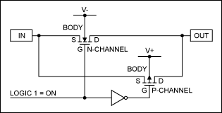
Figure 2. Schematic of the internal construction of a typical analog switch.
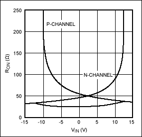
Figure 3. On-resistance vs. VIN for the n- and p-channel MOSFETs in Figure 2.
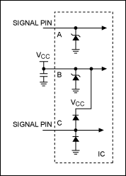
Figure 4. The typical ESD structure to protect ICs.
What do I need to consider when using a calibrated digital pot?
Although a CDPot draws very little current during operation, be sure to decouple the power with a capacitor. (See our Design Tools link to calculate self-resonance for effective decoupling at frequency. Go t www.maxim-ic.com/cal.)During the write to NV memory more current is used. Read the data sheet for the amount of current and time required for the write. Take care to allow enough time for the write to complete before removing power.
The wiper switches are tiny to reduce capacitance; drawing current through them creates nonlinearity. Observe the data sheet current limits for a part, but remember that the best design has zero wiper current.
Figure 5A shows the most common way to use a CDPot. It is better to add a series resistor to the ground end of the pot, as this prevents the pot from being adjusted so the negative op amp pin is at ground. Grounding the negative input effectively opens the feedback path. The open-loop gain of the op amp and circuit stray components will cause the op amp to oscillate. Remember that the wiper capacitance is also connected to the negative input of the op amp.
The wiper capacitor and the feedback portion of the pot resistor to the output form a lowpass filter pole. This filter is typically below a couple of hundred kilohertz. Above the filter cutoff frequency the feedback path again opens and oscillation will occur. This can be prevented by choosing an op amp with a gain bandwidth below the filter cutoff frequency. The pot's bandwidth can be extended as shown in application note 3081, "How to Increase the Bandwidth of Digital Potentiometers 10x to 100x." Figure 5B is an alternative design that uses the pot as an attenuator followed by a gain stage. This approach has the advantage of using the pot ratiometrically, that is, the effect of the end-to-end resistance tolerance is reduced and the temperature coefficient is improved. Figure 5C has the wiper connected to the op amp's negative input. Simply reversing the pot by connecting the wiper to the output pin of the op amp is a better design, as the op amp's output is more tolerant of the wiper capacitance than is the input.

Figure 5. Three common circuit blocks for digital pots.
 電子發(fā)燒友App




評論