Abstract: A step-up converter followed by an LDO regulator offers better battery life than a classic SEPIC design when operating from one lithium-ion cell. This is demonstrated with the MAX1800 multi-channel digital camera power IC for the step-up plus LDO design and a MAX668 for the SEPIC design.
There are a few different topologies that can be used for a step-up/step-down converter, the most popular being the single-ended primary inductance converter (SEPIC). Another option that is frequently overlooked is the step-up converter followed by a low dropout (LDO) regulator. Because a linear regulator is used for the step-down function, it is often assumed that the efficiency is poor. However, when making 3.3V from a single lithium-ion battery, the efficiency of this circuit can exceed that of an equivalent SEPIC circuit, with the added benefit of lower cost and less board space.
Figure 1 shows a portion of the MAX1800 five-channel step-up converter. The MAX1800 includes one synchronous rectified step-up converter, three step-up converter controllers, and a linear regulator controller. In this example, only the synchronous rectified step-up converter and linear regulator are discussed; however, it also applies to similar parts such as the MAX1703, the MAX1705, and the MAX1706.
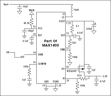
Figure 1. MAX1800 step-up/step-down circuit schematic.
The efficiency of this circuit versus load current over the typical lithium-ion battery range is shown in Figure 2. As expected, the efficiency at 4.2V is poor due to the loss through the LDO regulator.
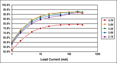
Figure 2. MAX1800 step-up/step-down efficiency.
The equivalent SEPIC circuit is shown in Figure 3. It uses the MAX668 step-up controller to make a SEPIC circuit. This circuit is more complex than the MAX1800 circuit shown above; however, more importantly, it requires either a single coupled inductor (transformer) or two separate inductors as well as a coupling capacitor. In the circuit shown, a coupled inductor is used.
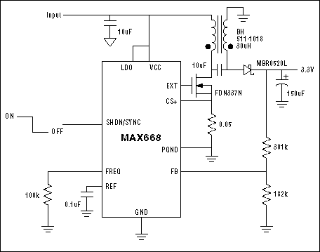
Figure 3. MAX668 SEPIC converter schematic.
The efficiency of this SEPIC circuit is shown in Figure 4. The efficiency of the SEPIC circuit in step-up mode is lower than that of the step-up +LDO circuit of the MAX1800, whereas the efficiency with a 4.2V input is higher.
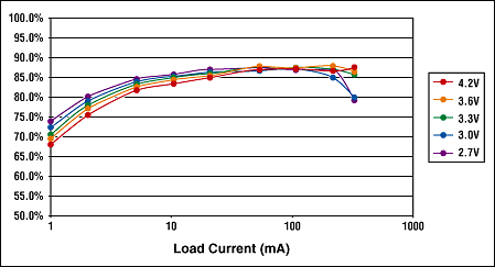
Figure 4. MAX668 SEPIC converter efficiency.
To determine which circuit will result in longer battery life, the 1C discharge curve of a typical lithium-ion cell, the Sony US18650, is used to weigh the efficiency curves with the amount of time that the battery will spend at that particular battery voltage. The discharge curve of the battery is shown in Figure 5, and the weighing factors are shown in Table 1.
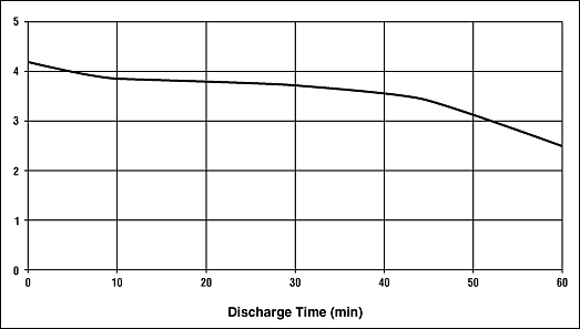
Figure 5. US18650 battery 1C discharge curve.
Table 1. Battery Voltage Weighing Factors
A composite efficiency curve using the data above and the weighing factors for input voltage is shown below. It can be seen that the peak efficiency of the step-up + LDO circuit exceeds that of the SEPIC, except for low currents.
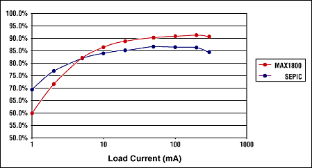
Figure 6. Composite efficiency of the MAX1800 and the SEPIC versus load current.
The efficiency of a step-up converter followed by an LDO regulator is typically considered an unsatisfactory option due to the perception of poor efficiency from the LDO. However, this perception is incorrect in the case where the typical battery voltage is near the regulated output voltage, as occurs when generating 3.3V from a single lithium-ion battery. Switching from a SEPIC circuit to a step-up + LDO circuit improves efficiency while also reducing the size and cost, making it clearly the better solution.
Additional Information:
- Quick View Data Sheet for the MAX668/MAX669
- Samples and Literature Order Form
- Technical Support: Power
There are a few different topologies that can be used for a step-up/step-down converter, the most popular being the single-ended primary inductance converter (SEPIC). Another option that is frequently overlooked is the step-up converter followed by a low dropout (LDO) regulator. Because a linear regulator is used for the step-down function, it is often assumed that the efficiency is poor. However, when making 3.3V from a single lithium-ion battery, the efficiency of this circuit can exceed that of an equivalent SEPIC circuit, with the added benefit of lower cost and less board space.
Figure 1 shows a portion of the MAX1800 five-channel step-up converter. The MAX1800 includes one synchronous rectified step-up converter, three step-up converter controllers, and a linear regulator controller. In this example, only the synchronous rectified step-up converter and linear regulator are discussed; however, it also applies to similar parts such as the MAX1703, the MAX1705, and the MAX1706.

Figure 1. MAX1800 step-up/step-down circuit schematic.
The efficiency of this circuit versus load current over the typical lithium-ion battery range is shown in Figure 2. As expected, the efficiency at 4.2V is poor due to the loss through the LDO regulator.

Figure 2. MAX1800 step-up/step-down efficiency.
The equivalent SEPIC circuit is shown in Figure 3. It uses the MAX668 step-up controller to make a SEPIC circuit. This circuit is more complex than the MAX1800 circuit shown above; however, more importantly, it requires either a single coupled inductor (transformer) or two separate inductors as well as a coupling capacitor. In the circuit shown, a coupled inductor is used.

Figure 3. MAX668 SEPIC converter schematic.
The efficiency of this SEPIC circuit is shown in Figure 4. The efficiency of the SEPIC circuit in step-up mode is lower than that of the step-up +LDO circuit of the MAX1800, whereas the efficiency with a 4.2V input is higher.

Figure 4. MAX668 SEPIC converter efficiency.
To determine which circuit will result in longer battery life, the 1C discharge curve of a typical lithium-ion cell, the Sony US18650, is used to weigh the efficiency curves with the amount of time that the battery will spend at that particular battery voltage. The discharge curve of the battery is shown in Figure 5, and the weighing factors are shown in Table 1.

Figure 5. US18650 battery 1C discharge curve.
Table 1. Battery Voltage Weighing Factors
| Battery Voltage | % of Battery Life |
|
|
|
|
|
|
|
|
|
|
|
|
|
|
|
A composite efficiency curve using the data above and the weighing factors for input voltage is shown below. It can be seen that the peak efficiency of the step-up + LDO circuit exceeds that of the SEPIC, except for low currents.

Figure 6. Composite efficiency of the MAX1800 and the SEPIC versus load current.
The efficiency of a step-up converter followed by an LDO regulator is typically considered an unsatisfactory option due to the perception of poor efficiency from the LDO. However, this perception is incorrect in the case where the typical battery voltage is near the regulated output voltage, as occurs when generating 3.3V from a single lithium-ion battery. Switching from a SEPIC circuit to a step-up + LDO circuit improves efficiency while also reducing the size and cost, making it clearly the better solution.
 電子發燒友App






評論