光電耦合器的三種檢測方法
2012-05-22 11:26:19 865
865 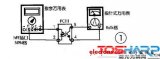
利用光電耦合器將高端電流檢測器的工作電壓擴展至1kV
2012-06-13 14:41:261042 
的控制電壓增大,經IC1內的控制電路處理后����,開關管的導體時間縮短,輸出端電壓下降到規定值����。當輸出端電壓下降時,穩壓控制過程相反����。光電耦合器IC2 2腳外接的C5是軟啟動電容����。開啟瞬間����,C5需要充電����,在它
2017-05-23 09:25:14
����。 由此可見����,只有在LED閃爍發光時����,光電耦合器才是好的,LED常亮和不亮時����,光電耦合器都是壞的����。 要想改變LED的閃爍頻率����,只需改動R1����、R2阻值或者改變電容C1的容量。
2021-05-20 06:37:24
措施。如可控硅所在的主電路一般是交流強電回路,電壓較高����,電流較大����,不易與微機直接相連,可應用光耦合器將微機控制信號與可控硅觸發電路進行隔離����。 在馬達控制電路中,也可采用光耦來把控制電路和馬達高壓電
2012-12-07 12:14:06
當采用光耦隔離數字信號進行控制系統設計時����,光電耦合器的傳輸特性����,即傳輸速度����,往往成為系統最大數據傳輸速率的決定因素。在許多總線式結構的工業測控系統中,為了防止各模塊之間的相互干擾,同時不降低通訊
2012-12-13 12:16:27
����,當電流流過地線時,會在地線上產生電壓����,這就是地線噪聲。在這個電壓的驅動下,會產生地線環路電流����,形成地環路干擾����。南于發送和接收設備共用一段地線,會形成公共阻抗耦合����。采用光電隔離器TLP521-4對發送
2011-01-17 20:15:16
光電耦合器在電子電路設計中是一種必不可少的器件����,其能夠將光能與電能進行互相轉換����,從而達到對電能進行自由掌控的目的����。并且隨著現代電源設備的多樣化發展,光電耦合器的應用場合也越來越廣泛����。在接下來的內容中,小編將為大家介紹光電耦合器在日常設計中的一些使用常識����,快來看看吧����。
2021-03-01 10:39:13
光耦合器的功用光耦合器的類型光電耦合器怎么測好壞
2021-01-08 07:37:30
光電耦合器是什么����?有哪些優點?有哪幾個參數����?
2021-06-07 06:44:31
光電耦合器運用廣泛,筆者依據光電耦合器特性,設計一個方便的測試光電耦合器電路,該電路簡單����、準確,使用方便。
2021-05-10 07:37:11
。輸入交流信號U1疊加在直流偏置之上����,經光電耦合器在100Ω電阻兩端產生電壓����,其中的交流信號耦合到運算放大器的反相端����,經放大后輸出交流信號U0.圖4����、線性放大電路3、電平轉移各種邏輯電路如工作電壓
2018-01-12 11:01:51
電路是否有+300V的直流電壓送到開關變壓器初級繞組的1腳上。如果有300V,再檢查啟動電路����、正反饋電路和集成電路IC801本身����。如果直流電壓不穩定,則檢查誤差檢測和誤差反饋電路����。光電耦合器的檢測光電
2011-07-21 11:03:46
的作用由于光耦種類繁多����,結構獨特����,優點突出����,因而其應用十分廣泛����,主要應用以下場合:(1) 在邏輯電路上的應用光電耦合器可以構成各種邏輯電路����,由于光電耦合器的抗干擾性能和隔離性能比晶體管好����,因此,由它
2012-12-12 12:30:20
光電耦合器如果不單獨供電,會影響單片機的輸出信號嗎����,昨天我試了一下����,讓光耦和單片機共電源����,信號通過光耦就沒有輸出了����,不是說光耦不單獨供電只會失去隔離作用嗎����?為什么會影響信號輸出呢����???����?
2017-09-04 10:44:58
耦合器的封裝形式一般有管形����、雙列直插式和光導纖維連接三種。圖1是三種系列的光電耦合器電路圖����。 光電耦合的主要特點如下: ●輸入和輸出端之間絕緣,其絕緣電阻一般都大于10 10Ω,耐壓一般可超過1kV
2021-05-25 07:35:53
儀器插座上����。 3、光電耦合器可作為線性耦合器使用����。 在發光二極管上提供一個偏置電流,再把信號電壓通過電阻耦合到發光二極管上����,這樣光電晶體管接收到的是在偏置電流上增、減變化的光信號����,其輸出電流將隨輸入
2012-06-04 11:08:38
。輸入交流信號U1疊加在直流偏置之上����,經光電耦合器在100Ω電阻兩端產生電壓����,其中的交流信號耦合到運算放大器的反相端����,經放大后輸出交流信號U0.圖4����、線性放大電路3����、電平轉移各種邏輯電路如工作電壓
2018-01-15 16:59:30
及各種家用電器等電路中.下面介紹最常見的應用電路.1.組成開關電路 圖1電路中,當輸入信號ui為低電平時����,晶體管V1處于截止狀態����,光電耦合器B1中發光二極管的電流近似為零����,輸出端
2009-08-21 08:39:58
耦合器的重要參數①隔離電容一般要求小于1PF②直流電流傳輸比CTR一般為20%--300%����,越接近常數則線性越好����,其大小反映光電耦合器的傳輸能力③輸入輸出間的絕緣電壓Viso(典型值:1—10KV
2012-06-11 17:21:59
電的轉換����?���;?b class="flag-6" style="color: red">工作特性(以光敏三極管為例)1����、共模抑制比很高 在光電耦合器內部����,由于發光管和受光器之間的耦合電容很?���。?pF以內)所以共模輸入電壓通過極間耦合電容對輸出電流的影響很小����,因而共模抑制比
2021-05-13 06:10:17
(I1)]=R3/R2����。由此可見����,利用T1和T2電流傳輸特性的對稱性����,利用反饋原理,可以很好的補償他們原來的非線性����。圖2 光電耦合器線性電路另一種模擬量傳輸的解決方法����,就是采用VFC(電壓頻率轉換
2012-12-13 12:24:34
光電耦合器驅動電路的設計與應用一����、實驗目的1.了解光耦合電路的工作原理2.學習并掌握光耦合驅動電路的設計方法3.光耦合電路的簡單應用二����、實驗原理光電耦合器是以光為媒介傳輸電信號的一種電一光一電轉換器
2012-06-29 11:08:24
吸塵器����、比如監控電焊機是否處于焊接狀態等等����。所謂的開關量:就是只有接通和斷開2種狀態����。開關量通過內置的觸點來實現����。開關量電流檢測器有以下特點:1 體積?���。鹤钚〉捏w積寬度41mm高度33mm厚度15mm
2021-02-19 22:30:19
轉換器件。它由發光源和受光器兩部分組成����。發光源的引腳為輸入端����,受光器的引腳為輸出端,在光電耦合器輸入端加電信號使發光源發光����,光的強度取決于激勵電流的大小,此光照射到封裝在一起的受光器上后����,因光電效應而
2018-08-22 11:46:41
避免陰極保護電流的流失?���! ∽鳛橹绷鞲綦x和交流導通裝置����,在一定的電壓范圍內阻止直流電流的導通����,比如-2~+2V或-3~+1V����,同時為交流電流提供低阻抗通道。當固態去耦合器兩個端子之間的電壓超過直流導
2020-12-01 16:20:33
8kV的瞬態峰值電壓實施穩健的隔離����。光電耦合器的加強絕緣性符合這些嚴格的要求,可在-40℃至+125℃的寬泛工作溫度范圍內提供安全的電氣信號隔離����。此外����,該器件的小型表面貼裝式封裝結構實現了高壓安全法規所要
2012-12-06 16:02:31
����。ACPL-W302的主要特點如下: ·ACPL-W302是一款峰值電流為0.4 A的隔離門驅動光電耦合器,而ACPL-W314則是一款峰值電流為0.6 A的隔離門驅動光電耦合器。這兩款產品在1000V的共模電壓
2018-08-27 15:24:34
Avago Technologies(安華高科技)宣布推出面向混合動力車(HEV)市場應用光電耦合器系列的最新產品����。Avago的新車用級ACPL-M46T是一個專門面向混合動力車應用所設計的1
2019-05-07 07:00:21
`IPP-7105IT是一種90度混合耦合器����,工作頻率范圍為1000至2500 MHz����。它的插入損耗小于0.50 dB����,隔離度大于14 dB����,VSWR小于1.30:1����。它可以處理高達200 W的CW
2021-03-17 15:03:12
MOC3051是摩托羅拉半導體研制的光電耦合器。 雙列直插6腳封裝。輸入驅動電壓3V����,電流60mA����;輸出驅動耐壓為交流240V����,最高600V����,驅動電流15mA����。可以與MOC3052互換����。
2021-05-20 07:27:17
PS2633是一款光電耦合器。它為雙列6腳封裝����,內含有1個單元光敏晶體管耗合器,光反射側:輸入最大電流=80mA,輸入最大電壓=6V,耗散功率=150mW,1.4V/10mA,極間電容=30pF
2021-04-23 07:43:02
PS2634是一款光電耦合器����。它為雙列6腳封裝����,內含有1個單元光敏晶體管耗合器,光反射側:輸入最大電流=80mA,輸入最大電壓=6V,耗散功率=150mW,1.4V/10mA,極間電容=30pF
2021-04-23 06:10:46
;nbsp; 3. 光電效應判斷法 仍以PC111光耦合器的檢測為例,檢測電路如圖2所示����。將萬用表置于R×1k電阻擋����,兩表筆分別接在光耦的輸出端{4}����、{5}腳����;然后
2010-06-11 20:07:05
光電耦合器的分類 由于光電耦合器的品種和類型非常多����,在光電子DATA手冊中,其型號超過上千種,通?���?梢园匆韵路椒ㄟM行分類: (1) 按光路徑分,可分為外光路光電耦合器(又稱光電斷續檢測器
2010-05-30 20:20:40
度好,絕緣電壓高����,高速大容量����,導通后壓降校光耦的耦合效率(即CTR)和隔離特性是其主要的誘人之處����,研發的產品種類可滿足不同場合的需求����,提高電子線路的可靠性����。光電耦合器的性能特點
2010-05-30 20:15:01
的紅外光后����,在三極管集電極中便有電流輸出����。圖1三極管輸出型光電耦合器的特點����,是具有很高的輸入輸出絕緣性能����,頻率響應可達300kHz����,開關時間數微秒可控硅輸出型光耦合器可控硅輸出型光耦合器的電路如圖1中
2018-08-21 14:42:03
DC2033A����,使用LT6110電纜/線下降補償器的演示板����。 LT6110是一款精密高端電流檢測器����,可通過檢測電阻監控負載電流����,并將檢測電壓轉換為吸收或源電流����。使用LT6110源極或吸收電流來控制
2020-08-12 09:58:27
來看看吧����?���! ∈紫纫獮榇蠹曳窒淼?���,是一種利用光耦合器設計的可逆計數顯示電路����,該電路圖的電路系統如下圖圖1所示����?���! D1 光耦可逆計數顯示電路 在圖1所展示的這種光耦合器可逆計數顯示電路中,其系統主要
2016-01-07 17:33:40
來看看吧����。首先要為大家分享的����,是一種利用光耦合器設計的可逆計數顯示電路,該電路圖的電路系統如下圖圖1所示����。在圖1所展示的這種光耦合器可逆計數顯示電路中,其系統主要利用光耦器件作為光傳感器進行制作,完成后
2017-01-04 16:35:23
本文介紹一些最常見的光電耦合器應用電路����。
2021-06-08 06:22:56
作用將失去意義;其次,當用光電耦合器來隔離輸入����、輸出通道時����,必須對所有的信號(包括數位量信號����、控制量信號、狀態信號)全部隔離����,使得被隔離的兩邊沒有任何電氣上的聯系,否則這種隔離也是沒有意義的。 第四
2014-08-20 16:32:22
:(1)根據功能的需要����,選擇不同的光耦類型,比如:如果是數據通信用����,那應該用高高速IC輸出型光耦����;而控制大電流的繼電器或燈泡����,應該用光繼電器 或可控硅繼電器����。(2)由于光電耦合器為信號單向傳輸器件,而電路
2018-06-12 17:50:26
FEBFOD8332是FOD8332智能柵極驅動器光電耦合器的評估板,是一款先進的2.5A輸出電流IGBT驅動光電耦合器����,可提供必要的關鍵保護����,以防止導致IGBT發生破壞性熱失控的故障
2019-04-30 09:06:13
FEBFOD8333是FOD8333智能柵極驅動器光電耦合器的評估板,是一款先進的2.5A輸出電流IGBT驅動光電耦合器,可提供必要的關鍵保護����,以防止導致IGBT發生破壞性熱失控的故障
2019-04-28 10:36:39
光耦合器,也稱為光隔離器或光電耦合器����,其已被用于實現電子電路電流隔離超過40年����。光耦合器使用LED和光電晶體管來實現信號通信����,而無需傳輸電流。作為一種低成本的解決方案,光耦合器一直很受歡迎。但考慮到數字隔離技術的進步����,光耦合器真的是實現RS-485系統電流隔離的最具成本效益的方法嗎?
2019-08-07 08:03:11
耦合器能夠傳輸連續變化的模擬電壓或模擬電流信號����,使其應用領域大為拓寬����。1 光耦合器的類型及性能特點1.1 光耦合器的類型光耦合器有雙列直插式、管式、光導纖維式等多種封裝形式����,其種類達數十種����。光
2012-12-10 14:26:10
����、延遲時間和存儲時間等參數。電流傳輸比是光耦合器的重要參數����,通常用直流電流傳輸比來表示。當輸出電壓保持恒定時����,它等于直流輸出電流IC與直流輸入電流IF的百分比����。使用光電耦合器主要是為了提供輸入電路和輸出電路
2012-12-18 15:26:12
的紅外光后,在三極管集電極中便有電流輸出����。圖1三極管輸出型光電耦合器的特點����,是具有很高的輸入輸出絕緣性能����,頻率響應可達300kHz����,開關時間數微秒可控硅輸出型光耦合器可控硅輸出型光耦合器的電路如圖1中
2018-08-21 21:46:32
各種型號光電耦合器穩定性檢測要點是什么
2021-05-13 06:46:29
如果想要利用光耦合器設計可逆計數顯示電路����,有什么簡單的方案呢����?
2021-03-07 08:08:49
本文筆者利用手中現有材料����,因陋就簡����,制作了一個光電控制過壓保護裝置����,其結構簡草����,動作靈敏����,效果比較滿意����。工作原理如附圖所示����,本裝置利用光電耦合器的通斷與否進行控制����。電壓正常時,光電耦合器幾乎無輸出����,BG管被反偏而截止����。
2021-04-23 07:08:41
這是一種超靈敏的失火檢測器����,采用光電二極管作為失火傳感器����,一旦檢測到設備的供電部分發生火花或失火,失火檢測器就馬上發出報警����,并立即切斷供電電源����。 附圖是失火檢測器電路����。
2021-05-07 06:54:11
(發光二極管)的電流變小����,內部“發光管”亮度下降����,“光敏管”的導通電阻也隨即增大,可進一步證明光電耦合器工作正常����。
2021-05-12 07:17:37
如何選擇光電耦合器光電耦合器的應用電路
2021-03-29 07:36:57
、適用范圍 安全電氣隔離用光電耦合器三����、檢驗依據及項目1. 檢驗依據:SJ/T10686-1995(VDE0884)《安全
2009-06-17 08:47:18
使用兩臺射頻變壓器(圖 2)����。其中����,變壓器 T1 用于檢測輸入和負載之間的主線電流����。另一變壓器 T2 用于檢測主線的對地電壓����。耦合系數取決于變壓器匝數比 N����。圖 2:基于射頻變壓器的定向耦合器拓撲使用兩臺
2021-10-13 09:59:13
用光電耦合器組成的多諧振蕩電路用光電耦合器組成的雙穩態電路用光電耦合器組成的整形電路用光電耦合器組成的斬波電路
2021-04-22 06:49:21
剛注冊就發求助帖,臉紅����。遇到一個問題����,由于對光電耦合器不了解����,所以不知道怎么做好����,特來求助����。問題是這樣的,要做一個可控整流的觸發信號板子����,需要測量三相工頻信號的相位����,打算用光電耦合器把工頻交流電
2012-02-27 11:13:18
`TLP181(GB-TPL,F,T)詳細參數[/td][/td][td]制造商Toshiba產品種類晶體管輸出光電耦合器配置1 Channel最大正向二極管電壓1.3 V最大輸入二極管電流50
2012-08-16 16:34:23
即用型固態繼電器(SSR)可靠且緊湊,但很難找到一款電流傳導能力高于幾百毫安的產品。比如����,若您需要一款隔離SSR來切換線路電壓����,那么您不得不采用功率FET自行構建一個SSR����。您可以采用光耦合器來提供
2018-10-26 11:00:39
`求光電耦合器optoiso1的封裝`
2013-01-04 13:58:13
請問光電耦合器 PC817在工作的時候電壓電流應該是多少?找了很多資料查不到!謝謝
2011-03-08 14:24:24
用光電耦合器組成的多諧振蕩電路用光電耦合器組成的雙穩態電路用光電耦合器組成的整形電路用光電耦合器組成的斬波電路
2021-04-07 06:11:59
����,具有有源啟動電路����,可降低待機功耗可擴展至更高的電壓和更高的功率范圍,以利用 SiC MOSFET 的高電壓功能電路板上包含兩個轉換器型號(PSR 和光耦合器反饋)恒定開關頻率類型的控制器,具有 1MHz 的最大開關頻率和 0% 至 96% 的占空比范圍
2018-10-15 14:56:46
����、耐沖擊����、容易和邏輯電路配合����,這使得它的應用很廣泛����。例如,在計算機數位通信及即時控制中作為信號隔離的接口器件����,可以大大增加其工作之可靠性����;在單片開關電源中����,利用線性光電耦合器可構成光耦回饋電路����,通過
2012-06-22 14:35:25
沖擊����、容易和邏輯電路配合����,這使得它的應用很廣泛����。例如����,在計算機數位通信及即時控制中作為信號隔離的接口器件����,可以大大增加其工作之可靠性����;在單片開關電源中,利用線性光電耦合器可構成光耦回饋電路����,通過調節
2012-06-22 14:38:10
的一般解決方案所不能相比的����。圖1 光電耦合器構成圖光電耦合器的優點是單向傳輸信號����、輸入端與輸出端在電氣上完全隔離����、輸出信號對輸入端無影響����、抗干擾能力強、工作穩定����、無觸點����、體積小����、使用壽命長、傳輸效率高
2012-05-31 10:58:37
封裝����。 FOD2743B產品特性:光耦合器、精密參考電壓源和誤差放大器在單個封裝中2.5V參考CTR 50%至100%����,1mA5,000V RMS隔離低溫系數最大50 ppm/°CFOD2743A: 容
2013-12-17 13:47:07
光電耦合器控制的振蕩器
2019-10-15 09:11:02
光電耦合器則用于提供隔離反饋����。Avago Technologies已將這些分立元件集成到ACPL-302J等智能柵極驅動光電耦合器中����。需要隔離的高端電源為柵極驅動器提供靜態和開關電源����,并為電流檢測提供
2018-08-18 12:05:14
集成的光電耦合器在cadence里面那個庫 或者符號是個啥
2012-06-24 13:37:55
共模抑制 (common mode rejection, CMR) 光電耦合器解決方案����,型號為 FOD3120 和 FOD3150����。這兩種產品是輸出電流分別為2.5A和1A的柵極驅動光電耦合器,具有
2012-12-06 16:16:33
和光電耦合器一樣����,它將發光二極管和光敏三極管組裝在一起并利用光信號來傳遞信息,實現電路信號的電->光->電的傳輸(光電耦合電路)����,這樣的目的是為了電路的輸入與電氣上處于完全隔離的狀態
2016-11-25 14:48:32
本文主要講述的是如何利用光電耦合器擴展高端電流檢測器的工作電壓至1kV����。
2009-05-06 10:05:45 33
33 常用光電耦合器型號參數
2008-07-09 21:54:446758 采用光電耦合器的保護電路圖
2009-07-17 14:39:571253 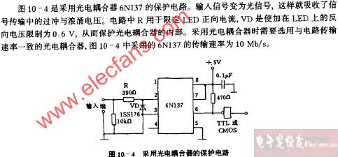
Avago推出業內最小型隔離電壓/電流檢測器
Avago Technologies(安華高科技)宣布����,推出兩款新微型化電壓/電流閥值檢測光電耦合器����,適合各種廣泛的工業控制應用����。ACPL-K370/K37
2009-11-25 09:10:18827 光電耦合器的工作原理是什么?
光電耦合器是一種把紅外光發射器件和紅外光接受器件以及信號處理電路等封裝在同一管座內的器件����。
2010-03-01 12:02:356041 本文將為你介紹光電耦合器的定義說明����、應用領域,以及判斷光電耦合器好壞的三種可靠的檢測方法����。
2012-02-09 11:26:037180 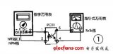
什么是高速光電耦合器?和光電耦合器一樣����,它將發光二極管和光敏三極管組裝在一起并利用光信號來傳遞信息����,實現電路信號的電->光->電的傳輸(光電耦合電路)
2012-03-14 17:28:222960 用光電耦合器組成的多諧振蕩電路
2012-06-04 13:43:04856 ATX電源的光電耦合器檢測好壞
2012-06-20 17:21:003430 本應用筆記介紹了電流檢測放大器與光耦的配合使用,能夠將工作電壓擴展至1,000V����,非常適合高壓應用����。電路利用光耦的隔離屏障分割1,000V系統的高端和地端。運算放大器用于消除光電二極管的
2012-06-25 11:48:451850 
如何利用光電耦合器隔離高電壓改善電動車鋰離子電池組的安全性
2016-01-06 17:24:200 如何利用光電耦合器隔離高電壓改善電動車鋰離子電池組的安全性����。
2016-05-24 17:12:500 100V 無光耦合反激式穩壓器可工作在 150oC, 提供高達 24W 功率和產生高達 1kV 輸出電壓
2021-03-19 12:05:1410 ����。由于光電耦合器工作環境的復雜性����,所以對光電耦合器的好壞檢測非常重要����。下面將介紹光電耦合器好壞檢測的步驟����。
2023-06-07 09:56:221831 通常����,在高壓端檢測直流電流非常困難����。大多數商用化的高端電流檢測IC能夠很好地工作在30V或40V����,新推出的器件(例如:MAX4080/4081)能夠檢測高達76V的電源����。如果需要工作在更高的電壓下����,則可利用檢流放大器與光耦相配合的方式����。高壓受限于光耦能夠承受的隔離電壓(圖1)����。
2023-06-12 17:23:14949 
光電耦合器是在什么時候、在什么情況下工作的����,其背后的原理是什么����?或者你在自己的電子工作中實際使用到光電耦合器時����,可能不知道如何選擇和使用它。由于經常有人將光耦與“光電晶體管”和“光電二極管”混淆����。因此����,在本文中將介紹什么是光電耦合器����。
2023-07-06 14:29:192396 
光電耦合器是一種將光信號轉換成電信號的裝置����。它由一個發光二極管和一個光敏三極管組成,通過光敏效應將光信號轉換為電壓信號����。在電子設備中����,光電耦合器常用于隔離電路����、信號傳輸和電氣噪聲抑制等方面����。本文將介紹如何選擇和使用光電耦合器。
2023-07-09 10:18:28547 光電耦合器是一種常見的電子元件,用于將電信號轉換為光信號或將光信號轉換為電信號����。在選擇和使用光電耦合器時����,有幾個關鍵因素需要考慮����。
2023-08-24 09:22:11292 光耦合器:
光耦合器、光電耦合器或光隔離器是一種利用光在兩個隔離電路之間傳輸電信號的元件。光隔離器可防止高電壓影響接收信號的系統����。光耦合器有四種常見類型,每種類型都具有紅外 LED 光源,但具有不同的光敏器件����。這四種光耦合器分別稱為:光電晶體管����、光電達林頓����、光電SCR 和光電雙向可控硅����,如下所示����。
2023-09-25 15:31:23820 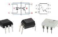
正在加载...
 電子發燒友App


 工商網監
工商網監
評論