降低精密放大器的電壓失調(diào)
Abstract: Voltage-offset errors in precision amplifiers are partly caused by input bias currents. This article analyzes the problem and proposes a solution based on resistor networks, both discrete and integrated. The analysis shows that integrated resistors can outperform the more costly discrete approach.
In precision electronics, amplifier stages must comply with precisely designed performance specifications. One problem encountered when designing these amplifiers is the voltage offset generated by currents flowing into the amplifier inputs. In this article, we first analyze the source of this offset, and then propose a solution based on integrated resistor networks.
Analyzing the Problem
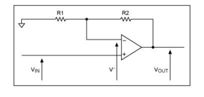
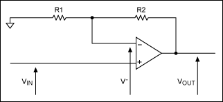
Before attempting to solve a problem, we need to understand its source. For that purpose, consider the simplified schematic for an ideal op amp (Figure 1).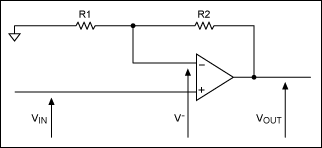
Figure 1. This simplified schematic depicts an ideal op-amp circuit.
The analysis of this circuit should be well known to first-year students (we assume zero current at the amplifier inputs):
Rearranging:
You can make the analysis more realistic by introducing a finite input resistance, which gives the op amp a finite input bias current. We model this effect with a current source on each input of the ideal op amp (Figure 2).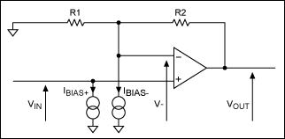
Figure 2. Current sources model input bias currents for the ideal op amp of Figure 1.
To analyze the effect of each of these current sources, assume that VIN = 0V. We assume that the impedance at VIN is small in relation to other impedances, so IBIAS+ will be shunted to ground and have no effect. Because VIN = 0V, V- must also equal 0V. Moreover, because both ends of R1 are at the same 0V potential, it can be eliminated from the analysis. Thus, we immediately see an unwanted output offset (VOUT), due to the input bias current (IBIAS-) and feedback resistor (R2):
VOUT = IBIAS- × R2
Solving the Problem
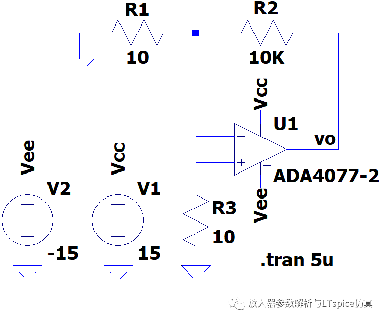
The circuit can be improved by adding one extra resistor (R3 in Figure 3). We need to examine the effect of this extra resistor, which causes the positive input to be offset negative by IBIAS+ × R3. You can, therefore, adjust R3 to nullify the effect of bias current into the negative input. It is reasonable, however, to make the approximation that positive and negative input bias currents are the same.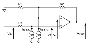
Figure 3. Adding a compensation resistor (R3) to the Figure 2 circuit cancels the effect of input bias currents.
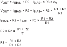
With VIN = 0, you can easily calculate VOUT by noting that we have a voltage adder circuit, i.e., the output voltage is the voltage applied to the positive terminal times the voltage gain, plus an offset due to input current leakage into the negative terminal. Because VIN = 0, any voltage applied to the positive terminal is due to leakage into that terminal, and R3:
If R3 equals the parallel combination of R1 and R2, the voltages generated by input bias currents should cancel. For the high-precision applications in which this technique is generally used, the resistors should be specified as follows:
- The ratio R2/R1 must have high precision in order to set a precision gain.
- The match between R3 and the parallel combination of R1 and R2 must also be high precision so errors introduced by the input bias currents are compensated.
- These resistors must track with temperature.
You can use either integrated or discrete resistors in the precision op-amp circuit of Figure 3.
Integrated Resistors
The MAX5421 (as an example) includes 15kΩ resistors and operates with a supply voltage of +5V or -5V. A similar part, the MAX5431, includes 57kΩ resistors and operates with a supply voltage of +15V or -15V. These devices not only include precision integrated resistors, but they also switch between the resistors. When the resistors are used to set gain in an op-amp circuit, this capability allows you to choose among programmable gains of 1, 2, 4, and 8.
Data sheets for these devices show that they exhibit constant resistance at the resistor-pair node for resistor ratios of 2, 4, and 8. If the ratio is 1, you see only the low resistance of the node. For all ratios, therefore, the matching resistor should equal the wiper resistance (Table 1).
Table 1. Matching Resistor Settings for MAX5421/MAX5431 Dividers
| ? | MAX5421 (VDD = +5V, VSS = -5V) |
MAX5431 (VDD = +15V, VSS = -15V) | |
| Wiper Resistance (kΩ, typ) | Rati 1 | 0.3 | 0.5 |
| Rati 2, 4, 8 | 8 | 14 | |
| Matching Resistance (kΩ, typ) | Rati 1 | 0.3 | 0.5 |
| Rati 2, 4, 8 | 8 | 14 | |
Resistor tolerances are shown in Table 2.
Table 2. Resistor Tolerances for MAX5421/MAX5431 Dividers
| Part | Divider Ratio Accuracy (±%, max) |
| MAX5421_A | 0.025 |
| MAX5421_B | 0.09 |
| MAX5421_C | 0.5 |
| MAX5431_A | 0.025 |
| MAX5431_B | 0.09 |
| MAX5431_C | 0.5 |
Note that these tolerances are guaranteed maximums over the full operating temperature range of -40°C to +85°C, which in turn guarantees the gain tolerance to a high level of precision. A typical integrated-resistor design (a precision amplifier) is shown in Figure 4.
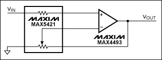
Figure 4. This precision amplifier combines precision resistors (MAX5421 ICs) with a general-purpose, rail-to-rail op amp (the MAX4495).
The main technical advantages of integrated resistor chips like the MAX5421 or MAX5431 are matching and temperature tracking between the resistors. You can then select a desired system gain by electronically switching among the gain-setting resistors.
The absolute resistance of an integrated resistor has a large tolerance. That is not a problem in these circuits, however, because gain values are precisely set by resistor ratios to within ±0.025%. If the matching resistor is external, you will have difficulty choosing the correct value, but integrated matching resistors make the task easy. Integrated resistors can be factory trimmed, and they track the gain-setting resistors precisely with temperature. Any tolerance in R1 and R2 also affects R3, so R3 should match the parallel combination of R1 and R2.
If your system does not require R3, you may be able to reduce costs by using digitally programmable, precision voltage-dividers like the MAX5420 and MAX5430. These devices have the same performance as the MAX5421 and MAX5431, but do not contain the matching resistor. For fixed-gain applications, consider the MAX5490, MAX5491, and MAX5492 resistor-dividers, which contain one fixed-ratio pair of resistors only and no matching resistor.
Discrete-Resistor Approach
Now, consider the gain-setting resistors for an alternate, discrete-component approach. The pair of discrete resistors must not only have a ratio tolerance of ±0.025%, but they must also track within this tolerance over the required temperature range. In practice, this means that each resistor must have a tolerance of 0.0125%. Resistor data sheets often specify an initial tolerance plus a temperature coefficient. We can therefore calculate the worst-case tolerance over the temperature range in question. The example below is based on specifications for an ultra-precision discrete resistor with a low temperature coefficient:
Initial tolerance: 0.005%
Temperature coefficient: 2ppm
Operating temperature range: -40°C to +85°C
The resistor tolerance over this range is, therefore:
RTOL = -(0.005 + (40 + 25) × 2 × 10-6)% (0.005 + (85 - 25) × 2 × 10-6)% RTOL = -0.018% 0.017%
To match the gain tolerance of an op amp with integrated resistors, you must use ultra-high-precision resistors like those above. Such discrete resistors are available, but they cost several dollars each. The resistor for input-offset matching is less critical, but its cost is prohibitive for a discrete component that comes even close to the performance of an integrated resistor. A single pair of resistors costs far more than a MAX542x or MAX543x (for example), which integrate all the resistors required for four gain settings, plus a matching resistor and all the switches and logic necessary to implement gain switching.
Conclusion
We have analyzed the problem of voltage-offset error caused by input bias currents in a precision system. By examining the discrete- vs. integrated-resistor approaches, we conclude that integrated resistors outperform their more costly discrete counterparts.
 電子發(fā)燒友App















評(píng)論