Cable-Loss Solutions
Abstract: This application note describes a method to compensate for cable loss, and allows test manufacturers to utilize the cost savings of high-loss cables without compromising the full performance capabilities of their systems.
Introduction
Application note 4303, "Impact of Cable Losses," discusses the mechanisms that lead to signal degradation from high-loss cables. The two main loss components presented are skin-effect and dielectric losses. Manufacturers, such as those who produce automatic test equipment (ATE), use many high-loss cables in their system to decrease their overall costs. As the speeds of these systems increase, the performance loss due to these cables creates a competitive disadvantage. Fortunately, electronic compensation can be designed to correct for the loss from these cables.
Possible Solutions for Cable Loss
One solution to the problem of cable loss is to use the best cables that you can afford, and that have the least negative impact on performance. Using the best cables possible is suitable for unique, high-cost systems, such as those used in military applications. However, a large cost is associated with this solution. Also, the size of the cables limits the number of cables in a system, and even good cables can have significant losses.
Another solution for cable loss is to design electronics that will not only drive the cable, but will also equalize the cable loss. This transfers the solution to the smaller pin electronics (PE) driving the cable, thus allowing the use of smaller, low-cost, high-loss cables. Electronic compensation also compensates PC board runs, relays, and connectors. Additionally, it allows the system to run at close to the full performance of the PE, regardless of the loss from the cables.
A final solution is to combine the two aforementioned solutions. However, the PE solution is the most practical, and it is the solution discussed in this application note.
Electronic Solution to Undesired Cable Loss
Figures 1 and 2 depict a representation of the effects of cable loss. These losses round of the edges of a waveform, or create what is sometimes referred to as "dribble up" on the final signal. It is this rounding of the edges that reduces the effective bandwidth of the system. This reduction in bandwidth is caused by the cable, and not the PE. In order to maximize system performance, we need to recover this bandwidth.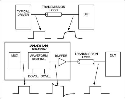
Figure 1. Conceptual representation of cable-loss correction for the driver.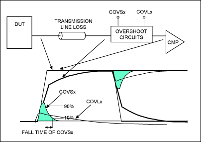
Figure 2. Cable-loss correction for the comparator path.
In order to correct this dribble-up effect and restore the bandwidth, we must find a way to restore the edges of the waveform back to the sharp, clean square wave coming directly from the driver. This correction must occur in the PE driving the cable. Figure 1 shows an extra circuit block called "waveform shaping" that effectively restores the edge by adding a controlled amount of overshoot. This edge restoration is not a simple overshoot circuit, which would give rise to unwanted edge effects, amplitude ripple, and overshoot depending on how much overshoot is applied. These unwanted affects create timing and skew errors that vary with frequency and amplitude.
Figure 2 shows in more detail the cable-loss correction approach that Maxim products take. This approach is based on two time constants. Figure 1 shows the correction in the driver path of the PE IC through the cable and then to the device under test (DUT). Figure 2 shows a similar correction from the DUT, back through the cable, and to the PE's comparators. Both the driver and comparator paths need to be corrected.
The cable-droop-compensation circuits add two peaking, single-time-constant decaying signals to the signal. The DOVSx input voltage controls the peaking level of the short-duration, overshoot voltage compensation, and the DOVLx input voltage controls the peaking level of the long-duration, overshoot voltage compensation. Both long- and short-duration compensation controls are limited to 10% overshoot correction. The two levels each have separate and fixed decay time constants. DOVSx compensation has a nominal decay time constant of 77ps, and DOVLx compensation has a nominal decay time constant of 1.5ns. COVSX and COVLX perform similar functions for the comparator path, as shown in Figure 2.
The MAX9957 dual 2000Mbps driver and the MAX9955 dual 2000Mbps comparator/terminator use the dual time constant approach displayed in Figures 1 and 2. There is a separate adjustment for each of the two time constants.
The MAX9979 dual 1100Mbps driver/PMU with level-setting calibration DACs uses a single control approach (see Table 1 and Figure 3). This approach also uses the dual-time-constant method, but combines the two time constants into a single 3-bit DAC.
Table 1. MAX9979 Cable-Droop-Compensation Control
| Serial Interface Bits | Droop Compensation (%) | ||
| CDRP2_ | CDRP1_ | CDRP0_ | |
| 0 | 0 | 0 | 0.0 |
| 0 | 0 | 1 | 1.5 |
| 0 | 1 | 0 | 3.0 |
| 0 | 1 | 1 | 4.5 |
| 1 | 0 | 0 | 6.0 |
| 1 | 0 | 1 | 7.5 |
| 1 | 1 | 0 | 9.0 |
| 1 | 1 | 1 | 10.5 |
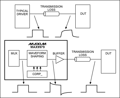
Figure 3. MAX9979 cable compensation.
MAX9979 Performance for Various Cables
The MAX9979 is a dual-channel PE with driver/comparator/load (DCL), PMU, and full level-setting capabilities. It dissipates approximately 1.1W per channel, and is specified at about 1Gbps toggling speed for a 3V waveform terminated into a 50Ω load.
Figures 4 through 9 were created as part of a bench test setup similar to Figure 3. These figures used the MAX9979 programmed for VDH = 3V and VDL = 0V to drive a 3V waveform terminated into a 50Ω load with the cables listed.
Figures 4 through 9 show very clearly the advantages of cable compensation vs. no cable compensation. Figures 8 and 9 are close to the real-world results of high-speed testers, clearly showing how the toggle rate, or bandwidth of a system, can be reduced by almost fifty percent. All of this loss occurs through the cables. The results can be even worse than is shown, because ATE uses cables with more loss than those listed in this application note. In addition, these testers have PCB runs, relays, and connectors in the same signal path, all of which add to the losses. The PE cable compensation in Maxim's ATE product line compensates for all of these items in the signal path.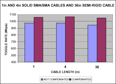
Figure 4. Toggle rate of solid and semi-rigid SMA cables before and after compensation.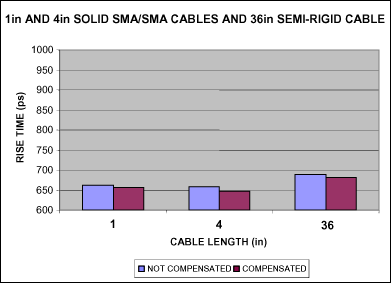
Figure 5. Rise time of solid and semi-rigid SMA cables before and after compensation.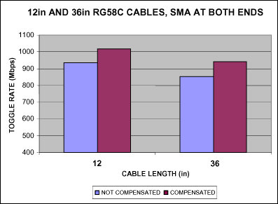
Figure 6. Toggle rate of RG58C cables before and after compensation.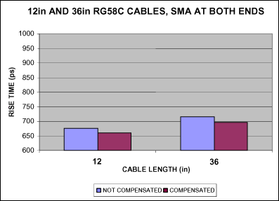
Figure 7. Rise time of RG58C cables before and after compensation.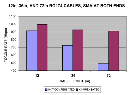
Figure 8. Toggle rate of RG174 cables before and after compensation.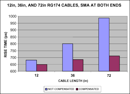
Figure 9. Rise time of RG174 cables before and after compensation.
When more closely analyzed, Figures 4 through 9 indicate the real problems of loss of toggle rate and increased rise times, especially for uncompensated paths. Depending on the length and quality of the selected cable, the application can lose more than 50% of the toggle rate in just the cable alone.
Notes:
- The cost of the solid SMA cables at the time of these bench tests was $130/foot. The cost of the semi-rigid cable was $30/foot, and the cost for RG58 and RG174 cables was $5/foot.
- The high-cost cables performed very well, even up to a length of 36in. But even these high-cost cables need compensation to obtain the highest toggle rates and smallest rise times.
- 12in, and especially 36in, RG58 cables show a drop-off in toggle rates and increased rise times, even when compensated. Uncompensated RG58 cables have much greater losses.
- Figures 8 and 9 depict that long, lossy cables without compensation greatly reduce the performance of a tester. Compensating these cables can recover the lost bandwidth or toggle rate to within 90% of the maximum possible from the driver.
- A system without cable compensation, which has PE drivers capable of 1000Mpbs speeds or higher, can lose up to 50% of its performance due to the loss from cables, relays, connectors, and PCB runs. Conversely, a system with PE that has cable compensation can achieve greater than 90% of the PE's performance.
- PE must have adjustable compensation. PE with simple overshoot added cannot compensate a range of cables, and can create timing errors due to edge and amplitude ripple affects that can vary with frequency and amplitude.
Figures 10 and 11 show the actual output waveforms for both the 6ft and 3ft RG174 cables. The data from Figures 8 and 9 data came directly from these outputs. The outputs show an uncompensated waveform, as well as partially/fully compensated and 1-bit overcompensated waveforms.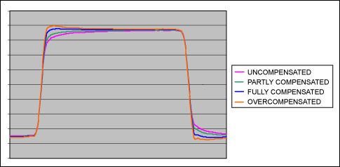
Figure 10. 6ft RG174 cable output waveforms. The four plots are for uncompensated, partly compensated, fully compensated, and overcompensated waveforms. (See Figures 8 and 9 for data.)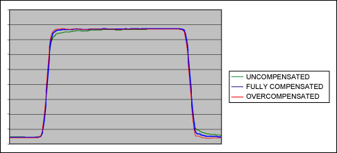
Figure 11. 3ft RG174 cable output waveforms. The three plots show uncompensated, fully compensated, and overcompensated waveforms. (See Figures 8 and 9 for data.)
The waveforms above show how careful design in the PE cable compensation can maintain the full fidelity of the waveform edges and even minimize amplitude ripples. This fidelity ensures that transient skews are maintained correctly and optimally for all frequencies and amplitudes.
Summary of Bench Test Results
Figures 4 through 11 reinforce the theory, discussion/analysis, and proof work done in the laboratory. The captured data represents cables of a higher quality than what are normally used in an ATE system. Clearly, without cable compensation schemes in place, systems cannot operate at the same performance level as the PE. It is also obvious that designing cable compensation into PE can recover almost 100% of the optimum performance and achieve nearly the maximum speed available from the PE.
Designing cable compensation into the electronic drivers allows the use of low-cost, high-loss cables, while maintaining the full throughput of the PE. Adding this compensation into the electronics increases the per unit pin cost; however, the performance advantages and lower cost cables inevitably justify this additional cost, and should prove to be less costly overall.
 電子發燒友App





評論