Reduce System Cost for Advanced Powerline Monitoring by Leveraging High-Performance, Simultaneous-Sampling ADCs
Abstract:?Rising power demands and a focus on energy conservation are driving increased investment in the global power-delivery infrastructure. As a result, advanced powerline monitoring systems have become a critical element of the new "smart grids" for both single- and multiphase applications. With system performance requirements growing more stringent, designers are turning to simultaneous-sampling, multichannel, high-performance ADCs for their powerline monitoring or multichannel SCADA (supervisory control and data acquisition) systems.
A similar article appeared on the EDN Magazine website on August 18, 2009.
Introduction
Advanced powerline monitoring systems combine power-supply monitoring, load balancing, protection, and metering functions in one system. This approach allows the power utilities to deliver, and the customers to consume, grid power more efficiently. Along with efficient delivery, the advanced powerline monitoring systems predict maintenance needs; detect and respond to fault conditions; record and allow for dynamic load balancing and energy conservation; monitor (and control) the quality of power delivery; and help protect equipment.To implement these monitoring systems, ADCs (analog-to-digital converters) are needed to monitor the voltage and current on multiple phases. However, to meet the stringent requirements of the various standards and to measure and optimize power-factor losses, these converters must be synchronized to ensure that they sample three phases (plus neutral) simultaneously. Synchronizing individual converters can be difficult, so vendors offer multiple simultaneous-sampling ADCs in a single package. If a more highly integrated solution is needed, another option is to integrate the simultaneous-sampling converters in a custom ASIC.
Performance Measurements—Local Standards and International Requirements
The development and widespread adoption of advanced powerline monitoring systems is complex due to varying international standards defining the precision of energy measurement. The measurement characteristics of the delivered energy must comply with local standards or international requirements. The EU (European Union) standards EN 50160, IEC 62053, and IEC 61850 dictate the minimum accuracy needed for a modern multichannel ADC system used in power-system monitoring and metering. Powerline monitoring is also impacted by the increasingly stringent accuracy requirements associated with real-time power-delivery monitoring, fault detection and protection, and dynamic load balancing. As an example, the EU standard IEC 62053 Class 0.2 (which is increasingly used as a common standard worldwide) requires meter precision to be 0.2% of nominal current and voltage. For power-factor accuracy measurement, phase matching should be 0.1% or better.Not only is the minimum accuracy specified, but international and local standards also dictate the sample rate needed for a modern system used in powerline monitoring and metering. There is now a need for rigorous analysis of multiple high-order harmonics of the AC supply and for detection of high-speed fault conditions such as instantaneous spikes and brownouts. Consequently, these applications typically require accurate, simultaneous multichannel measurement over a wide dynamic range of up to 90dB with a sample rate of 16ksps or higher.
Many countries around the globe have adopted versions of the EU standards, so these standards serve as a good example of the measurement requirements which the system must meet. Table 1 summarizes the EN 50160 requirements.
Table 1. EN 50160 Energy Specifications
| Supply Voltage Phenomenon | Acceptable Limits | Measurement Interval | Monitor Period | Acceptance Percentage (%) |
| Grid Frequency | 49.5Hz to 50.5Hz, 47Hz to 52Hz | 10s | 1 week | 95, 100 |
| Slow Voltage Changes | 230V ±10% | 10min | 1 week | 95 |
| Voltage Sags or Dips (≤ 1min) | 10 to 1000 times per year (under 85% of nominal) | 10ms | 1 year | 100 |
| Short Interruptions (≤ 3min) | 10 to 100 times per year (under 1% of nominal) | 10ms | 1 year | 100 |
| Accidental, Long Interruptions (> 3min) | 10 to 50 times per year (under 1% of nominal) | 10ms | 1 year | 100 |
| Temporary Overvoltage (Line-to-Ground) | Mostly < 1.5kV | 10ms | — | 100 |
| Transient Overvoltages (Line-to-Ground) | Mostly < 6kV | — | — | 100 |
| Voltage Unbalance | Mostly 2%, but occasionally 3% | 10min | 1 week | 95 |
| Harmonic Voltages | 8% THD | 10min | 1 week | 95 |
For the harmonic voltage, the EN 50160 mandates measurement up to the 25th-order harmonic of 50Hz/60Hz voltages. However, for various nonlinear loads, such as inductive motors and switching power-supply drives, measurements must be done for up to the 127th-order harmonic of 50Hz/60Hz voltage supply.
It is also important to note that emerging standards like IEC61850 recommend the recording of power-system transient events with 256 samples per AC cycle or higher.
A Typical Power-Grid Monitoring Application
Standard throughout the world, 3-phase power is distributed using what is called a "wye connection." The term "wye" refers to three voltages that are offset in phase from each other by one-third of a cycle (120°). A fourth wire, or neutral line, is often used to accommodate unbalanced loads. If loads on each of the three phases are equal, the system is balanced and no current flows though the neutral line. A typical power-grid monitoring scheme is shown in Figure 1. Each phase's power (voltage and current) measurements are obtained by a current transformer (CT) and a voltage transformer (a potential transformer, PT, in power-distribution nomenclature). The complete system comprises four such pairs (one pair for each of the three phases plus neutral).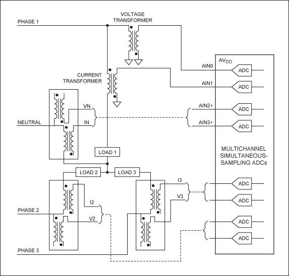
Figure 1. Typical power-grid monitoring application using simultaneous-sampling ADCs.
As Figure 1 illustrates, the ADCs simultaneously measure the three phases and neutral voltages and currents. By performing digital processing on the sampled and digitally converted data, the active-, reactive-, apparent-energy, and power-factor parameters can be found and the line loads can be dynamically adjusted to correct for power factor. The result is increased power efficiency. The execution of a FFT (fast Fourier transform) on the sampled data can allow frequency and harmonic distortion metering to be achieved, while highlighting information such as system losses and the effects of unwanted noise.
Power-Monitoring System Requirements
Power-monitoring equipment must measure instantaneous current and voltage values with sample rates up to 60Hz × 256 samples, or greater than 15,360sps (samples per second), to accommodate the standard's requirements. This requirement and the need for precision up to 90dB form the basis for selecting the ADC used in the system.The ADC's dynamic range for voltage measurement can be calculated from the maximum and nominal voltages to be monitored, and from the required accuracy for power measurements. For example, if a design must measure a 1.5kV (1500V) temporary overvoltage (under a fault condition) with a nominal 220V voltage measurement and 0.2% specified accuracy, then the total dynamic range of the voltage-measurement subsystem will need to be at least:
20log ((1500/220) × 2000) = 83dBNote: In all these calculations, the required design accuracy is assumed to be 0.05%, which is better than the standard's 0.2% accuracy requirements. This design margin is used to ensure compliance to the standard.
Current-sensing requirements also affect ADC specifications. If the design requirements for power monitoring are the typical 100A:10A (10A nominal and 100A maximum) and Class 0.2 (0.2%), then the total dynamic range of the current-measurement subsystem will need to be:
20log ((100/10) × 2000) = 86dBThese examples clearly demonstrate the need for higher performance in today's ADCs. To achieve an 86dB dynamic range, a 16-bit ADC with sampling rates of 16ksps or higher is essential. To ensure accurate 3-phase and neutral wye system current and voltage measurements, the ADC must sample up to eight channels simultaneously (four voltage and four current). Additionally, the ability to correct the current and voltage transformer-induced phase shift (or delays) is critical for systems trying to measure and correct power factor to maximize power efficiency.
ADC Alternatives
When selecting the right ADC for a power-grid monitoring application, designers must look beyond sample rates and standard requirements. Today they must also consider factors like effective input impedance (ZIN), signal-phase adjustment, and a small package size. Given these many system requirements, designers are turning to simultaneous-sampling, multichannel, high-performance ADCs for their powerline monitoring or multichannel SCADA (supervisory control and data acquisition) systems.Several ADC solutions meet the rigorous standards of these power-grid monitoring applications. A majority of these targeted solutions are 6-channel, 16-bit simultaneous-sampling ADCs with sample rates up to 250ksps.
Several companies offer chips with up to six low-power 250ksps SAR (successive-approximation register)-type ADCs. Maxim offers the MAX11046*, which integrates eight high-precision, low-power, 16-bit, 250ksps SAR ADCs in a single package. The MAX11046 achieves greater than 90dB signal-to-noise ratio.
Effective Input Impedance (ZIN)
ZIN is dictated by the input capacitance and sampling frequency:ZIN = 1/(CIN × FSAMPLE)Where FSAMPLE is the sampling frequency and CIN = 15pF.
If the ADC has a high ZIN like the MAX11046, it can interface directly with voltage and current-measurement transformers. That interface often eliminates the need for external precision instrumentation amplifiers, or buffers. The design therefore saves system cost, board area, and power. Figure 2 shows an application example for a single-phase monitoring system based on the MAX11046 EV (evaluation) kit board connected to powerline monitor transformers. The schematic shows the simple cost and space-efficient interface between the powerline transformers and the simultaneous-sampling, multichannel data converter. For a three-phase power system, this circuitry is replicated for each phase and the neutral.
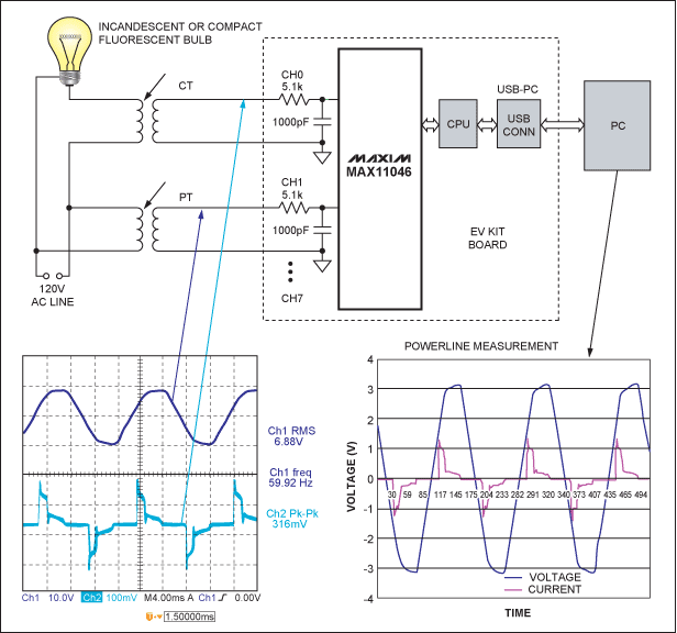
Figure 2. Multichannel simultaneous-sampling ADCs such as the Maxim MAX11046 simplify the design of advanced power-monitoring systems. A single-phase monitoring solution is shown in this example.
Signal-Phase Adjustment
As high voltage goes through the transformer and transitions to a lower voltage, a phase shift (or delay) occurs. This delay creates a significant problem for power-management or power-monitoring applications. To address this, designers can adjust phase in software at the backend or they can realign the signals inside the ADC upfront. Deskewing the voltage and current signals allows for true and accurate measurement of the power factor in the wye configuration. Shifts in phase from the 120o separation of the three phases represent lost power. Once the power factor is accurately measured, it can be corrected to make the grid exponentially more efficient.Traditionally, signal-phase adjustment using simultaneous-sampling, multichannel 16-bit ADCs has been addressed digitally as a postprocessing step performed on the ADC's output data. Maxim's MAX11046 high-precision data converter handles phase adjustment in this manner. With such an ADC, continuous software overhead is required to address signal-phase adjustment.
Some of today's ADC solutions offer input-phase adjustments of 0 to 333μs with the delay independently settable per channel in 1.33μs steps. This design eliminates the software overhead mentioned above. One such device, the 24-bit, 4-channel MAX11040 sigma-delta ADC, provides this capability plus high-precision, simultaneous sampling of as many as 32 channels using a built-in cascade feature. Each channel includes an adjustable sampling phase that permits internal compensation for phase shift due to external transformers or filters at the inputs. An active-low SYNC input allows periodic alignment of the conversion timing for up to eight devices with a remote timing source.
Small Package Size
In many power-grid monitoring applications, physical size matters. Often there is a need to monitor multiple polyphase supply lines, particularly in power-distribution centers. When examining the board area consumed by an ADC per-channel implementation, there are differences in the solutions available today. For example, the MAX11040 solution uses 15.9mm2 per channel, which is less than half the area of solutions offered by other venders.High packing density of the ADCs allows more channels to be physically loaded on a PCB. This helps minimize the overall size, power consumption, and cost of the measurement systems.
Overvoltage Protection
The optimal system design must also prevent system failures from overloads or other line disturbances. The MAX11040 and other devices in its family have built-in overvoltage protection (similar to ESD protection) through the use of clamp diodes set for 6V and an internal logic circuit that sets a fault bit if high voltage is detected. Other ADC vendors have their own approaches, but external diode protection is typically used.Detecting power-grid shorts and opens is a primary function of many of these protection systems using ADCs. Detection is done by looking at the data coming from the ADC. Criteria for when to trip a relay are complex and highly proprietary to each monitoring system vendor. Nonetheless, it is generally agreed that it is as bad to trip in a false situation as it is not to trip in a fault situation.
Conclusion
Rising worldwide power demands are driving rapid investment in the power-delivery infrastructure or "smart grid." By integrating power-supply monitoring, dynamic load balancing, protection and metering functions, and advanced powerline monitoring systems, utility companies (and customers) can monitor, deliver, consume, and control grid power more efficiently.Complicating the development and widespread adoption of these power-grid monitoring systems are the varying standards and agency requirements. Stringent specifications, such as the EN50160, IEC62053, and IEC61850 standards, dictate the precision energy measurement, the minimum accuracy, and sample rate needed for real-time power-delivery monitoring, fault-detection and protection, and dynamic load balancing. These standard requirements create clear criteria for the ADCs utilized in such a modern multichannel ADC system. Other factors, including effective input impedance (ZIN), signal-phase adjustment, and small package size, also influence ADC selection.
Today's high-performance, simultaneous-sampling ADCs are optimized for three-phase power (plus neutral) monitoring and measurement systems. These devices are a natural choice for high-density designs that need to provide high performance while reducing total system cost and minimizing board area.
*Future product—contact factory for availability.
 電子發燒友App




評論