Fans are a necessary part of many thermal management strategies, but fans can cause excessive levels of audible noise when operating at full speed. Adjusting the cooling-fan speed as a function of temperature is a good way to reduce acoustic noise in a system. The standard way to make that adjustment (shown in simplified form in Figure 1) uses an IC that combines temperature sensing with a PWM output, which in turn controls the power supply for a DC brushless fan.
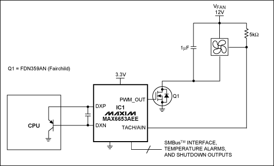
Figure 1. The fan controller IC1 generates a PWM signal with a duty cycle that increases with increasing temperature. The PWM waveform controls fan speed by modulating the fan's power supply.
The fan controller (IC1) measures the temperature of an external diode-connected transistor, which can be a discrete transistor or the thermal-sense diode on an Intel? or AMD? microprocessor. Then in response to the measured temperature, the fan controller automatically adjusts the duty cycle of its PWM output waveform. Fan-control characteristics such as the temperature at which the fan starts spinning, the initial PWM duty cycle, and the slope of the temperature/duty-cycle relationship, are programmed over the SMBus. As a result, at low temperatures the fan spins slowly (or not at all), producing little acoustic noise. As the system temperature increases, producing a need for more cooling, the fan speeds up. Changes in fan speed are gradual, so if the fan-speed controller is programmed properly, users will probably not notice the circuit's operation.
The PWM output drives power transistor Q2, which modulates the fan's power supply. PWM modulation is simple, inexpensive, and efficient, but it applies a series of pulses to the fan's power supply. Accompanying each PWM pulse is a slight physical perturbation of the fan assembly, which can cause an increase in fan noise, usually in the form of a "clicking" sound at the PWM frequency. Depending on the fan's design, this noise may be nearly inaudible, or may be moderately loud and distracting to users.
To minimize this excess acoustic noise, drive the fan with a DC voltage. DC drive eliminates PWM pulses and the consequent added fan noise. The circuit of Figure 2 is essentially an inverting amplifier with high output-current capability. It filters the PWM waveform from IC1 and provides a current- and voltage-boosted output that varies linearly with duty cycle. It also inverts the PWM waveform, so that 100% drive to the fan occurs when the PWM output is at 0V.
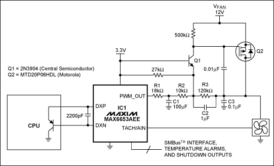
Figure 2. This circuit improves the standard approach of Figure 1 by including a lowpass filter that converts the PWM output of IC1 to a DC power supply for the cooling fan. Replacing IC1 with a fan controller that has a higher PWM frequency (such as the MAX6639) allows the value of C1 to be reduced significantly.
The fan's nominal power-supply voltage for full-speed operation is 12V. The PWM-to-linear circuit operates from 12V, and IC1 operates at 3.3V. Because Q1's base is at 3.3V, its emitter voltage is approximately 2.7V. Q1's emitter serves as the amplifier's inverting input. R1, R2, and R3 provide feedback around the amplifier. Note that most of the current through R1 and R2 also flows through R3, providing voltage gain between the PWM output and fan. To accommodate that gain, the drain of Q2 is driven to assume the corresponding voltage. Capacitors C1 and C3 produce an effective DC output voltage by filtering the PWM waveform. A small amount of ripple is inaudible, and therefore acceptable. If necessary, however, you can alter the capacitor values to trade ripple voltage against capacitor size.
Note that C1 in Figure 2 is a rather large value (100μF) because it is used to filter the 93.5Hz maximum PWM frequency signal from IC1. Replacing IC1 with a fan-controller IC that produces a higher frequency PWM allows the value of C1 to be reduced. Examples of fan controllers with higher PWM frequencies include the MAX6615/MAX6616 (35kHz), MAX6639 (25kHz), MAX6641 (35kHz), and MAX6678 (35kHz). Using any of these ICs with the PWM frequency set to its maximum value allows reduction of C1 to around 1μF.
Figure 3 shows the output voltage vs. PWM duty cycle for this circuit. The transfer function is reasonably linear and well-behaved. To minimize output ripple, set IC1's PWM output frequency to the highest available value. Set the PWM output polarity to provide 0V at the PWM output for a 100% duty cycle. Therefore, when driving the fan, be sure to choose a duty cycle that results in an output voltage at least 40% of full scale. Note that the 40% minimum voltage is a guideline; different fan models will differ in their ability to operate from low supply voltages.
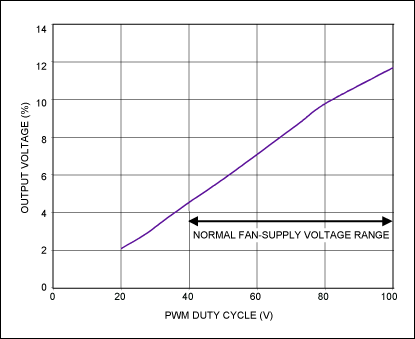
Figure 3. Output voltage vs. input duty cycle for the circuit of Figure 2.
A similar version of this article appeared in the February 21, 2005 issue of EE Times magazine.
AMD is a registered trademark of Advanced Micro Devices, Inc.
Intel is a registered trademark of Intel Corporation.
SMBus is a trademark of Intel Corp.
 電子發燒友App







評論