Abstract: A unique circuit for inverting the output signal of a temperature sensor such as the MAX6607 and MAX6608 without using precision components or references. The inverted signal is referenced to an analog-to-digital converter (ADC) reference voltage for conversion. The MAX4236 op amp and two discrete components is all that is required to complete the circuit. The gain of the temperature sensor is maintained at unity as opposed to traditional op amp inverting circuits results in a gain of two and the requirement for precision components.
To invert the output of an analog temperature sensor (in producing a signal for a temperature-compensated power supply, for example) you might choose an inverting op amp, but that approach may require two carefully picked feedback resistors to meet the specified accuracy.
An inverting op amp operates with a noise gain of two, which produces twice as much output offset voltage as does a unity-gain buffer. Figure 1 depicts the traditional method for inverting an analog output such as that of a temperature sensor. It also depicts a single-supply system, which has become the norm. As reference voltage for the op amp's non-inverting input, the circuit also requires a voltage source, a voltage reference, or a resistive voltage divider.
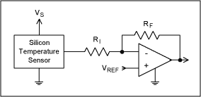
Figure 1. The need for a pair of matched resistors handicaps the classic inverting-amplifier circuit.
As an alternative, the circuit of Figure 2 inverts the output of an analog temperature sensor precisely, without need for precision components. Connecting the sensor output to the amplifier's inverting input forces the sensor's ground pin to swing negative with respect to the reference voltage. Thus, at the temperature corresponding to a sensor output of 0V, the circuit output equals VREF. The circuit output implements the exact inverse of the scale factor of the temperature sensor, swinging negative with respect to the reference. When the sensor output is 750mV at 25°C (typical for a 10mV/°C sensor with 500mV offset at 0°C), the circuit output is VREF - 750 mV. Components R and C ensure stability in the amplifier.
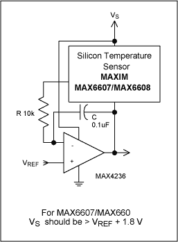
Figure 2. This connection provides a precise inversion of the temperature-sensor output without the need for precision components.
Voltage across the temperature sensor must never drop below the sensor's minimum rated supply voltage. That minimum occurs at the coldest temperature expected, for which the sensor's negative pin is driven most positive. However, that restriction is eased by the low minimum operating voltage of the MAX6607/MAX6608 devices shown (1.8V). Thus, VS must be at least 1.8 volts greater than VREF at all times. See Table 1. Because this circuit varies the sensor's supply voltage, the sensor introduces a slight additional error in proportion to its power supply rejection ratio.
Table 1. Maximum VREF for various supply voltages
A similar version of this article appeared in the May 20, 2002 issue of Planet Analog magazine.
To invert the output of an analog temperature sensor (in producing a signal for a temperature-compensated power supply, for example) you might choose an inverting op amp, but that approach may require two carefully picked feedback resistors to meet the specified accuracy.
An inverting op amp operates with a noise gain of two, which produces twice as much output offset voltage as does a unity-gain buffer. Figure 1 depicts the traditional method for inverting an analog output such as that of a temperature sensor. It also depicts a single-supply system, which has become the norm. As reference voltage for the op amp's non-inverting input, the circuit also requires a voltage source, a voltage reference, or a resistive voltage divider.

Figure 1. The need for a pair of matched resistors handicaps the classic inverting-amplifier circuit.
As an alternative, the circuit of Figure 2 inverts the output of an analog temperature sensor precisely, without need for precision components. Connecting the sensor output to the amplifier's inverting input forces the sensor's ground pin to swing negative with respect to the reference voltage. Thus, at the temperature corresponding to a sensor output of 0V, the circuit output equals VREF. The circuit output implements the exact inverse of the scale factor of the temperature sensor, swinging negative with respect to the reference. When the sensor output is 750mV at 25°C (typical for a 10mV/°C sensor with 500mV offset at 0°C), the circuit output is VREF - 750 mV. Components R and C ensure stability in the amplifier.

Figure 2. This connection provides a precise inversion of the temperature-sensor output without the need for precision components.
Voltage across the temperature sensor must never drop below the sensor's minimum rated supply voltage. That minimum occurs at the coldest temperature expected, for which the sensor's negative pin is driven most positive. However, that restriction is eased by the low minimum operating voltage of the MAX6607/MAX6608 devices shown (1.8V). Thus, VS must be at least 1.8 volts greater than VREF at all times. See Table 1. Because this circuit varies the sensor's supply voltage, the sensor introduces a slight additional error in proportion to its power supply rejection ratio.
Table 1. Maximum VREF for various supply voltages
| VS | MAX VREF |
| 5 | 3.2 |
| 3.3 | 1.5 |
| 3 | 1.2 |
| 2.7 | 0.9 |
A similar version of this article appeared in the May 20, 2002 issue of Planet Analog magazine.
 電子發燒友App









評論