The MAX1298/MAX1299 analog-to-digital converters with an internal temperature sensor have a guaranteed ±1°C accuracy over the extended temperature range (-40°C to 85°C), the best temperature-sensor accuracy over this range of any part in the industry. This article explains how to actually attain this level of accuracy given the thermal and mechanical system being used.
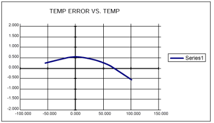
The MAX1298/MAX1299's typical internal temperature error versus temperature is shown in Figure 1. Achieving this level of accuracy requires careful attention to the thermal and mechanical aspects of the system design.
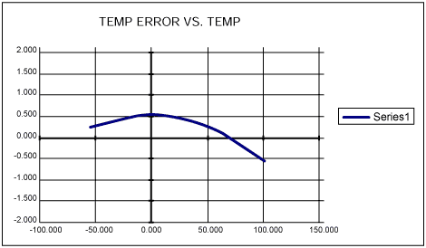
Figure 1. MAX1298/MAX1299 internal temperature. error versus temperature (°C)
Because the package of the MAX1298/MAX1299 must be mechanically and thermally connected to the object whose temperature is to be measured (OM), there will be a flow of heat between the device and the object measured if there is a temperature difference between them. Also, because the package of the MAX1298/MAX1299 temperature sensor (TS) must be mechanically and thermally connected to a power supply (PS), there will be a flow of heat between the MAX1298/MAX1299 and the PS if there is a temperature difference between them. There will also be a flow of heat between the MAX1298/MAX1299 and the ambient environment (AE) if there is a temperature difference between them.
A thermally "lumped " system is defined as follows:
Table 1. Thermal Conductivity
Equation 1 can be simplified t
Obtaining an estimate of the thermal conductivity between the MAX1298/MAX1299 temperature sensor and the ambient environment (KTSAE) is a little more involved, because the radiation from our 2cm × 2cm temperature sensor (TS) PC board to the ambient environment (AE) is not truly a thermally lumped process but more like a thermally distributed process. You can estimate KTSAE by assuming that the PC board is actually a blackbody radiator. This allows the use of the Stefan-Boltzmann formula, which uses just the surface area of the radiator (A) and the fourth power of the two temperatures, TTS and TAE:
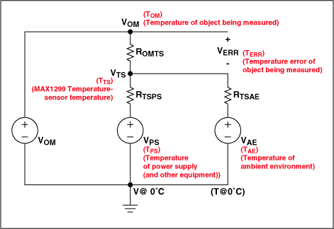
Figure 2. Electrical analog of thermal system.
ROMTS represents the thermal resistance between the measured object's heat reservoir (VOM) and the temperature sensor. ROMTS has a thermal resistance of 1/KOMTS. Similarly, RTSPS represents the thermal resistance between the temperature sensor and the power-supply heat reservoir (VPS). RTSPS has a thermal resistance of 1/KTSPS. Finally, RTSAE represents the thermal resistance between the temperature sensor and the ambient-environment heat reservoir (VAE). RTSAE has a thermal resistance of 1/KTSAE. Now assume for the moment that the temperature sensor does not generate any heat of its own. Then notice that the temperature at the temperature sensor (TTS) is analogous to VTS, the voltage at the temperature-sensor node. We can compute this as a function of the various components:
As an example, let's make TOM = 75 °C, TPS = 30 °C, and TAE = 25 °C, so VOM = 75V, VPS = 30V, and VAE = 25V.
To find the values of the K terms, let's make the following assumptions:
KOMTS is due to a 1mm-thick, 20mm x 20mm area application of silicon heatsink compound applied between the temperature-sensor PC board and the object being measured. The K value of a popular silicone heatsink compound is 18 × 10-4 Cal /(deg C × cm × sec) = 0.75 J/ (deg C × m × sec). Therefore:
We found the temperature at the temperature sensor to be 74.177 °C for this example. The temperature error TERR = TTS - TOM = 74.177 - 75.000 = -0.823 °C. This is a fairly large error, but because it depends on the various temperatures it can be somewhat higher or lower. To observe this, take equation 4 and replace the voltages with their associated temperatures:
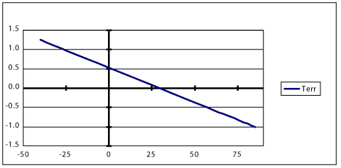
Figure 3. TERR (°C) vs. TOM (°C).
As can be seen in Figure 3, the temperature error due to the thermal characteristics of the system can be larger than the error due to the MAX1298/MAX1299 temperature sensor. There are several things that can be done to help reduce this error (TERR):
The MAX1298/MAX1299's typical internal temperature error versus temperature is shown in Figure 1. Achieving this level of accuracy requires careful attention to the thermal and mechanical aspects of the system design.

Figure 1. MAX1298/MAX1299 internal temperature. error versus temperature (°C)
Because the package of the MAX1298/MAX1299 must be mechanically and thermally connected to the object whose temperature is to be measured (OM), there will be a flow of heat between the device and the object measured if there is a temperature difference between them. Also, because the package of the MAX1298/MAX1299 temperature sensor (TS) must be mechanically and thermally connected to a power supply (PS), there will be a flow of heat between the MAX1298/MAX1299 and the PS if there is a temperature difference between them. There will also be a flow of heat between the MAX1298/MAX1299 and the ambient environment (AE) if there is a temperature difference between them.
A thermally "lumped " system is defined as follows:
- A system that is interconnected by thermally conductive material that is thermally insulated in the radial direction—meaning that conductivity in the radial direction of the conductor is very low compared to the conductivity along its length (an example of this is insulated copper wire), or
- A system interconnected by thermally conducting silicon "grease."
(dQ/dt)12 = (T1- T2) × K × A12/(x2-x1) Joules/secIn the equation above, T1 and T2 are the temperatures (in °C) of object 1 and object 2, respectively, K is the thermal conductivity of the interconnect material [in Joules/(°C × meter × sec)], A12 is the cross-sectional area of the interconnecting material (in meters2), and (x2-x1) is the length of the interconnecting material (in meters). For the thermal conductivity (K) values for various materials, see the table below.
(Equation 1)
?
Table 1. Thermal Conductivity
|
|
|
| Silver |
|
| Copper |
|
| Gold |
|
| Silicon Heatsink Compound |
|
Equation 1 can be simplified t
(dQ/dt)12 = (T1- T2) × K12 Joules/secIn this equation, K12 is the particular thermal conductivity of the interconnection between object 1 and object 2 in Joules/(°C × sec).
(Equation 2)
Obtaining an estimate of the thermal conductivity between the MAX1298/MAX1299 temperature sensor and the ambient environment (KTSAE) is a little more involved, because the radiation from our 2cm × 2cm temperature sensor (TS) PC board to the ambient environment (AE) is not truly a thermally lumped process but more like a thermally distributed process. You can estimate KTSAE by assuming that the PC board is actually a blackbody radiator. This allows the use of the Stefan-Boltzmann formula, which uses just the surface area of the radiator (A) and the fourth power of the two temperatures, TTS and TAE:
KTSAE = A × 56.697 × (TTS 4 - TAE 4) × 10-9 J/secNow, for the sake of simplification, let's make the assumption that the object measured, the power supply, and the ambient environment act as large heat reservoirs, so that their temperatures won't change when heat is exchanged between them. Note that we cannot make this assumption for the MAX1298/MAX1299 temperature sensor because of its diminutive size and mass. We can now make a thermal model of the system using an electrical schematic as an analog (see Figure 2).
(Equation 3)

Figure 2. Electrical analog of thermal system.
ROMTS represents the thermal resistance between the measured object's heat reservoir (VOM) and the temperature sensor. ROMTS has a thermal resistance of 1/KOMTS. Similarly, RTSPS represents the thermal resistance between the temperature sensor and the power-supply heat reservoir (VPS). RTSPS has a thermal resistance of 1/KTSPS. Finally, RTSAE represents the thermal resistance between the temperature sensor and the ambient-environment heat reservoir (VAE). RTSAE has a thermal resistance of 1/KTSAE. Now assume for the moment that the temperature sensor does not generate any heat of its own. Then notice that the temperature at the temperature sensor (TTS) is analogous to VTS, the voltage at the temperature-sensor node. We can compute this as a function of the various components:
VTS = (VOM × KOMTS + VPS × KTSPS + VAE × KTSAE) / (KOMTS + KTSPS + KTSAE)Now let's make our life easier by selecting a 1:1 relationship between VOM and TOM. So, let VOM = TOM (°C), VPS = TPS (°C), and VAE = TAE (°C).
(Equation 4)
As an example, let's make TOM = 75 °C, TPS = 30 °C, and TAE = 25 °C, so VOM = 75V, VPS = 30V, and VAE = 25V.
To find the values of the K terms, let's make the following assumptions:
KOMTS is due to a 1mm-thick, 20mm x 20mm area application of silicon heatsink compound applied between the temperature-sensor PC board and the object being measured. The K value of a popular silicone heatsink compound is 18 × 10-4 Cal /(deg C × cm × sec) = 0.75 J/ (deg C × m × sec). Therefore:
KOMTS = 0.75 × (0.02 × 0.02)/1 × 10-3 = 0.3 Joules/(°C × second)KTSPS is due to a 4m long, 16 conductor (assuming that all the pins on the MAX1298/MAX1299 are being used), pi × (1mm)2 cross-section area of insulated copper cable. (This is a 16-conductor 4-meters-long 1mm-radius copper cable. These cables mostly have circular, not square, conductors, thus the pi × r2 area term. The MAX1298 pins are so short that their contribution is insignificant.) Then
(Equation 5)
KTSPS = 380 J/(m × s × °C) × (16 × pi × (1 × 10⁻³m)2)/4m = 0.0048 Joules/( °C × second)KTSAE is due to a 20mm x 20mm PC board connected directly to the ambient environment. From equation 3, KTSAE = (0.02 × 0.02) × 56.697 nW/meter2/°C4 × (TTS 4 - TAE 4). If we assume the thermal drop across the silicon heatsink compound is relatively small, then TTS ~ TOM and
(Equation 6)
KTSAE ~ (0.02m × 0.02m) × 56.697 × 10(-9 × (TOM 4 - TAE 4) = 709uJ/(°C × sec)Now plugging the calculated values for the K terms and the voltage values we selected above, we obtain the following:
(Equation 7)
VTP = (75 × 0.3 + 30 × 0.0048 + 25 × 0.000709) / (0.3 + 0.0048 + 0.000709) = 74.177VFinally, let's consider the case where the MAX1298/MAX1299 is operating at maximum power to see what effect this has on TERR. The maximum MAX1298/MAX1299 power = 5.5V × 500uA = 2.75mW. A good estimate of this term in the TERR equation is to add a delta TERR to the TERR term such that delta TERR is ~ 2.75mW / KOMTS = 2.7 × 10⁻³ / 0.3 = 9 × 10⁻³ °C ~ +.01 °C. Thus, the MAX1298/MAX1299 contribution to TERR can be safely ignored in this setup.
(Equation 8)
We found the temperature at the temperature sensor to be 74.177 °C for this example. The temperature error TERR = TTS - TOM = 74.177 - 75.000 = -0.823 °C. This is a fairly large error, but because it depends on the various temperatures it can be somewhat higher or lower. To observe this, take equation 4 and replace the voltages with their associated temperatures:
TTP = (TOM × KOMTS + TPS × KTSPS + TAE × KTSAE) / (KOMTS + KTSPS + KTSAE)Therefore:
(Equation 9)
TERR = TTS - TOM = [(TOM × KOMTS + TPS × KTSPS + TAE × KTSAE) / (KOMTS + KTSPS + KTSAE)] - TOMA plot of TERR versus TOM for this system is shown in Figure 3.
(Equation 10)

Figure 3. TERR (°C) vs. TOM (°C).
As can be seen in Figure 3, the temperature error due to the thermal characteristics of the system can be larger than the error due to the MAX1298/MAX1299 temperature sensor. There are several things that can be done to help reduce this error (TERR):
- Reduce the number of conductors between the power supply (and other equipment that is at ambient temperature) and the temperature sensor. This can be accomplished by not using all of the functions available with the MAX1298/MAX1299.
- Increase the temperature-sensor PC-board dimensions. A metal plane that is not electrically connected to the MAX1298/MAX1299 and covers both sides of the board will increase KTSOM if it is screwed in tightly to the measured object. The MAX1298/MAX1299 should be on the measured-object side of the PC board.
- Lengthen the conductors connecting the temperature sensor to the power supply (and other equipment that is at or about the ambient temperature). This can be accomplished by coiling up the excess wire near the power-supply end of the cable. The power-supply end of the cable is at a lower temperature than the temperature-sensor end and thus any "radial" heat radiated out of the extra insulator will have a smaller delta T driving it. Note that the MAX1298/MAX1299 power supplies will need to have local capacitive decoupling on the temperature-sensor PC board, because there is a large amount of series inductance in the cable.
- Transmit your digital signals through an alternate channel, like opto-isolators or fiber-optic cables. This alternate-channel serial data can be recovered locally at the temperature sensor. This will help reduce the number of conductors needed (see number 1 above).
- Power the MAX1298/MAX1299 with a battery. This, combined with number 3 above, can in principle completely eliminate the conductors and make TERR negligible. This is a feasible option due to the small power requirement and the many power-down options of the MAX1298/MAX1299.
 電子發燒友App







評論