This application note is a courtesy of Michel St-Hilaire and Marc Desjardins from XyryX Technologies, Quebec city, Province of Quebec, Canada.
Introduction
The DS1620 Digital Thermometer and Thermostat provides 9-bit temperature readings which indicate the temperature of the device. With three thermal alarm outputs, the DS1620 can also act as a thermostat. Temperature settings and temperature readings are all communicated to/from the DS1620 over a simple 3-wire interface.However, the SPI interface found on many Motorola processors cannot directly communicate with the 3-wire interface found on the DS1620. First, the data flow to and from the DS1620 is multiplexed on only one pin (DQ) while SPI needs two separate signals (MOSI, MISO).
Second, most SPI interfaces are limited to 8-bit data transfer, complicating sending and receiving the 9-bit temperature readings to and from the DS1620. In addition, the DS1620's interface transfers LSB first, while SPI is an MSB-first communication protocol.
Lastly, the RST-bar is unlike a CS-bar (chip select) signal in that RST-bar must be high from the beginning of a transfer (protocol) to the end of all transfer of data (e.g. 9th bit transferred when reading temperature value).
Despite all these constraints, a fairly simple solution can be found which allows an SPI interface to communicate with a DS1620. This technique is described in this application note.
SPI Interface
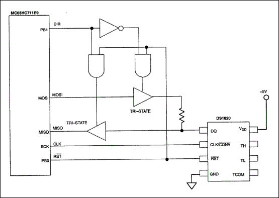
The circuit shown in Figure 1 can be used to control data flow direction with an SPI bus interfaced to a DS1620. This circuit could be integrated into a small PAL if desired.The purpose of the DIR signal is to select between sending data to or receiving data from the DS1620. When DIR is low, the DS1620 is receiving data; if DIR is high, data is being read by the SPI controller.
The resistor is necessary to prevent contention between the output of the tri-state buffer on the MOSI line and the DQ pin of the DS1620, because after a READ command protocol has been received by the DS1620, its DQ pin changes direction from input to output in a few hundred nanoseconds. This time is much too short for the microprocessor controlling the DIR signal to take action.
When connecting multiple peripherals on the same SPI bus, the MISO signal must be tri-stated when the DS1620 is not accessed to prevent contention with the MISO signal of other peripherals. That is why the RST-bar signal is necessary in the logic which determines the data direction.
Note that the SPI clock is wired directly to the CLK pin of the DS1620. The software has to take care of the polarity and phase of the SPI clock to be compatible with the CLK timing requirements of the DS1620.

Figure 1. SPI to DS1620 interface circuit.
Software for the Interface
While the hardware for the interface is relatively straightforward, the rest of the SPI/DS1620 interface must be handled by software. The following example shows a way to do this in the case of reading the temperature from the DS1620. This code fragment assumes that the DS1620 has already been initialized, that the configuration register is set up properly, and that temperature conversions have been initiated. See the DS1620 data sheet for details on these operating modes.Before accessing the DS1620, the DIR signal must be asserted low for a WRITE transfer to occur. RST-bar must be driven high to enable the DS1620. The SPI controller sends out the protocol (eight bits long) to the DS1620. Again, note that SPI sends information MSB first, while the DS1620 communicates LSB first. In order to accomplish this, a software "mirror" should be used to reverse the bit order. An example of such a function is given by:
unsigned char mirror(unsigned char value)
{
     unsigned char i;
     unsigned char value_mirrored = 0x00;

     for (i=0;i<=7;i++)
     {
        value_mirrored = value_mirrored | (((value>>i)&0x01)<<(7-i));
}
return (value_mirrored);
}
With the protocol sent, the DIR is changed from low to high (indicating now a READ transfer) because the DS1620 is ready to send out the 9-bit value. Note that RST-bar is still high. The SPI controller reads the first eight bits of the 9-bit value (LSB first). The software has to "mirror" the received byte. The 9th bit (followed by seven dummy bits) is pulled out by making another READ transfer and keeping DIR and RST-bar as they are. When the second byte is received, the software again mirrors it and pulls RST-bar low, terminating communication with the DS1620.#define RST_bit 0 /* PB0 */
#define RST_port PORTB
#define DIR_bit 1 /* PB1 */
#define DIR_port PORTB
#define READ_TEMP_CMD 0xAA
unsigned int read_temp(void)
{
unsigned char temp_value_lo;
unsigned char temp_value_hi;
DIR_port = DIR_port & ~(1<<DIR_bit); /* DIR = L WRITE mode */
RST_port = RST_port | (1<<RST_bit); /* RST = HI: DS1620 enabled */
SPDR = mirror(READ_TEMP_CMD); /* Send protocol to DS1620 */
DIR_port = DIR_port | (1<<DIR_bit); /* DIR = HI: READ mode */
while ((SPSR & (1<<SPIF_bit)) == 0); /* Wait for SPI flag = ready */
temp_value_lo = mirror(SPDR); /* Receive 8 lowest bits */
temp_value_hi = mirror(SPDR); /* Receive 8 highest bits */
RST_port = RST_port & ~(1<<RST_bit); /* RST = L Temp. reading done */
return ((temp_value_hi<<8)+temp_value_lo); /* Return the 9-bit value */
}


用戶評論
共 0 條評論