How to Replace a DS1213 SmartSocket with an Equivalent-Density NV SRAM Module
Abstract: The DS1213 SmartSocket products have reached end of life, and can be replaced using a pin-compatible, equivalent-density 5V NV SRAM module product. With that replacement module product, the customer will be installing a complete, one-piece memory solution. IntroductionThe DS1213 SmartSocket products have reached end of life, and can be replaced using a pin-compatible, equivalent-density 5V NV SRAM module product. With that replacement module product, the customer will be installing a complete, one-piece memory solution guaranteed to provide at least 10 years of data retention life. The replacement product easily doubles the operational lifetime of the equivalent SmartSocket-based configuration.Replacement DecisionsWith the diminishing production of PDIP SRAMs of any density, the decision to identify a replacement product may be accelerated by procurement problems to locate compatible memory chips. The DS12xx-family of NV SRAM modules includes a very low-power SRAM component, which eliminates the two-component procurement requirement of the past. The "AB" version of those modules allows for a ±5% operational power-supply tolerance, which matches the electrical characteristics of the previous DS1213-equipped installation.In existing applications, a DS1213 SmartSocket and some version of a customer-procured SRAM provide a nonvolatile memory array for data storage in the absence of external power. The SRAM specification will be a good reference for identifying two replacement criteria that will dictate which speed grade of module to purchase: the memory density and the memory performance-based information. The customer should initially research the memory configuration presently installed, and then refer to Table 1 for an appropriate replacement component. Table 1. SmartSocket Replacement Products
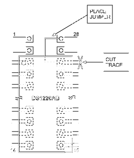
From the SRAM markings and/or specification, there should be some indication of the functional read access time of that memory. This parameter is generally designated by a numeric extension of the part number; it annotates the maximum time, in nanoseconds, that data can be read out of the component (example: -55, -70, -100, -120, etc.). Some manufacturers will truncate the speed grade information on their brand information, so the electrical specification will be the most comprehensive reference document. DS1213 SmartSockets are set from the factory for a power-supply tolerance of 5V ±5%, resulting in write protection below 4.75V. The equivalent power-supply tolerance in the DS12xx- family of NV SRAM modules has the AB suffix, as listed in Table 1. In some rare applications, the DS1213 SmartSocket may have been modified to use a 5V ±10% tolerance. In those applications, the replacement part number would be the same DS12xx part number with an "AD" suffix. DS1213 SmartSockets are rated for 0°C to +70°C operation, which is matched by the DS12xx- family of commercial-temperature products. If the industrial temperature range (-40°C to +85°C) is needed, then module products, designated as "IND," are also available in any NV SRAM memory density. Refer to the ordering information for that specific module product. DS1213 SmartSockets are manufactured using tin-lead (SnPb 63/37) solder to attach the internal components. If desired, Pb-free (100% matte tin) module products, designated by a plus sign (+), are also available in any memory density. Refer to the ordering information for that specific module product. Due to the internal battery, neither the DS1213 SmartSockets nor any listed DS12xx- family of NV SRAM modules can tolerate convection reflow soldering. Wave or hand soldering is recommended. Considerations for the DS1213B with 16kb SRAMThe DS1213B SmartSocket has 28 pins, but the DS1220 memory component has only 24 pins. PCB modifications are necessary t jumper VCC from trace 28 down to trace 26; and isolate trace 26. The DS1220 module is then installed by justifying the new component to the bottom (ground) end of socket. After removing the SmartSocket from the board, perform the necessary board modifications. Then install the DS1220AB justified to the bottom (ground) end, just as the SRAM was previously positioned in the socket. DS1220AB component pin 1 should align with the PCB trace previously associated with the SmartSocket pin 3, as shown in Figure 1.The original PCB traces that were aligned to SmartSocket pins 1, 2, 27, and 28 will be unused. There is an alternative to this board modification: install a DS1225AB memory module. The system will only utilize one-quarter of the memory array, but the changes are less complicated.  Figure 1. Placement of a 24-pin module on a 28-pin land pattern. (Not drawn to scale.) Considerations for the DS1213D with 256kb SRAMThe DS1213D SmartSocket has 32 pins, but the DS1230 memory component has only 28 pins. PCB modifications are necessary t jumper VCC from trace 32 down to trace 30; and isolate trace 30. The DS1230 module is then installed by justifying the new component to the bottom (ground) end of the socket. After removing the SmartSocket from the board, perform the necessary board modifications. Then install the DS1230AB justified to the bottom (ground) end, just as the SRAM was previously positioned in the socket. DS1230AB component pin 1 should align with the PCB trace previously associated with the SmartSocket pin 3, as shown in Figure 2.The original PCB traces aligned to SmartSocket pins 1, 2, 31, and 32 will be unused. There is also an alternative to this board modification: install a DS1245AB memory module. The system will only utilize one-quarter of the memory array, but the changes are less complicated.  Figure 2. Placement of a 28-pin module on a 32-pin land pattern. (Not drawn to scale.) |
 電子發(fā)燒友App














評(píng)論