簡介
這實際上不是任何產(chǎn)品或公共項目(!)-它是我設計用來幫助我評估太陽能電池板以及它們在何時工作的方式的給電池充電。通常,這需要大量的萬用表,如果您必須不斷更換面板,這會有些麻煩。因此,我決定建立一個可以幫助我的專業(yè)工具。這就是我想要的!
可攜帶!很難測試內部的太陽能電池板
能夠登錄到SD卡進行長期數(shù)據(jù)分析(稍后添加)
保持太陽能電池板電壓的跟蹤
》
保持電池電壓
保持流經(jīng)面板到充電器的電流量
我想過是否必須構建此電池,有人可能會覺得我的筆記有用。但是,本文檔的主要目的是演示如何使用adafruit商店中隨附的機柜。

此設計適用于?6V面板,單個鋰聚合物電池和充電器。它可以很容易地適應任何類型的面板和充電器,您只需要調整電阻分壓器等等!
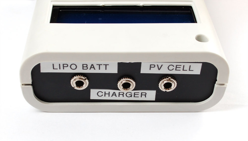
請注意,該項目不是太陽能數(shù)據(jù)記錄器。您確實需要使用電池為它供電,這僅用于分析面板!
零件列表
Arduino,外殼和顯示器:
Adafruit Metro 328P(與Arduino Uno兼容)
Arduino的外殼
16x2 LCD
0.1“接頭和電位計與LCD配套使用,如果您從Adafruit商店購買,則包括在內
數(shù)據(jù)記錄屏蔽或原型屏蔽(在本教程中我們實際上并未進行任何數(shù)據(jù)記錄,因此,如果您只想查看而不跟蹤,則原型屏蔽就可以了。)
高級母跳線(您也可以只需使用普通線,但我們希望能夠輕松拆卸LCD。)
模擬電子設備!
3 x 10K電阻器
1 x 47K電阻
1 x 15K電阻
1 x 1.0K電阻
3 x 3.5mm接線端子
0.1 ohm(電流檢測)電阻器
8引腳DIP雙軌至軌輸入/輸出運算放大器(TS922正常工作)
用于運算放大器的8引腳DIP插座
3 x單聲道3.5毫米唱機插孔
3 x單聲道3.5毫米唱機插頭
然后,當然是要記錄的東西。您可以替代其他類型的電池和充電器。
6V 1W太陽能電池板
Lipoly充電器
鋰聚合物電池
如果要將它帶到外面,則需要便攜式電源,我們喜歡AA的電源,但是如果不打算長時間使用,也可以使用9V。
6 x AA電池座
帶開關的9V座
9V電池夾
模擬物
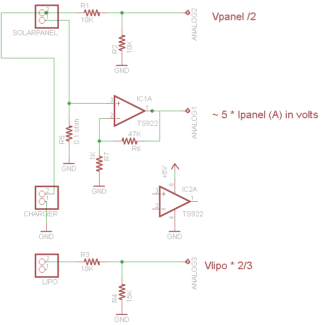
有一些模擬的東西。最容易理解的兩個部分是由 R1 和 R2 和 R3 和 R4 制成的分壓器。 R1 和 R2 取6V太陽能電池板電壓并將其除以2(只需使R1 = R2),以使模擬轉換器的輸入低于3.3V。同樣, R3 和 R4 采用高達4.2V的限制電壓并將其除以3/5,以使其降至3.3V以下,因此我們可以跟蹤該電壓
更復雜的部分是用于測量電流消耗的運算放大器。我們在太陽能電池板的負極線和地面之間插入一個0.1歐姆的電阻,這樣我們就可以通過測量跨過電阻的電流來測量流過電池板的電流。 1 A的電流變?yōu)?00mV(我們的面板的電流不能超過300mA,也就是30mV)。足夠低,不會影響太陽能電池板的充電能力。但是,30mV確實很低,這是我們期望的面板最大值。我們使用同相放大器將電壓放大到更大且更易于管理。特別是。該放大器將電壓乘以 1 + R6/R7 = 48x!這會將我們的30mV最大信號變?yōu)?.5V。我們不進行更多放大的原因是,我希望能夠使用更大的面板,該面板可以提供500mA或更高的電流,因此會有一些裕量。
通常,我使用的電阻器在我的桌子上(0.1歐姆除外,這個值很重要),因此請隨時調整這些值。
如果我今天要構建此項目,則應使用合適的高端電流傳感器,例如精確的INA219,可以測量高壓,并且易于使用!
可悲的是,當我最初設計此項目時,它并不在手邊
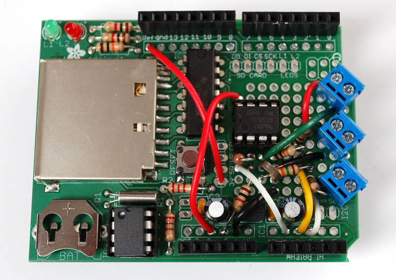
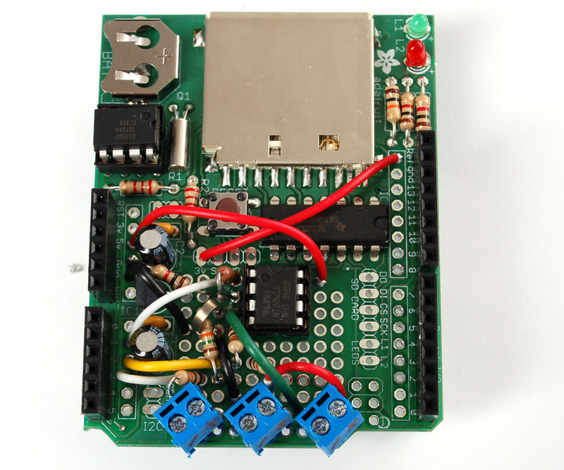
現(xiàn)在可以使用烙鐵了!這實際上是最煩人的部分。如果您不需要數(shù)據(jù)記錄-僅需LCD反饋,則將其焊接到Protoshield上會感到更加高興,因為有更多的空間。單擊圖片以放大照片。要進行焊接,我們在導線上彎曲并在鉗夾之前仔細焊接在一起。有時很難遵循,所以要慢慢檢查每一步的工作。
請注意,我們將 ARef 綁定到3.3v以獲得更穩(wěn)定的模擬讀數(shù)-特別是在使用電池時動力的便攜式記錄儀!

套管
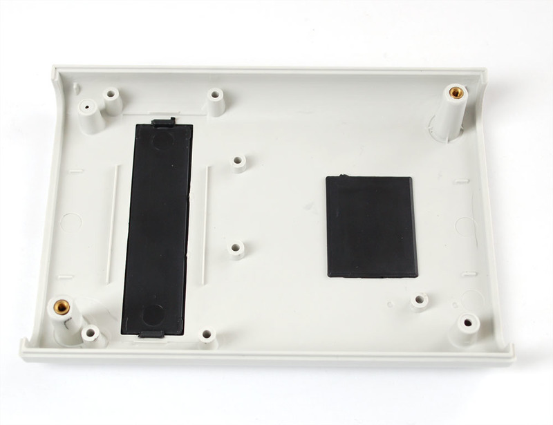
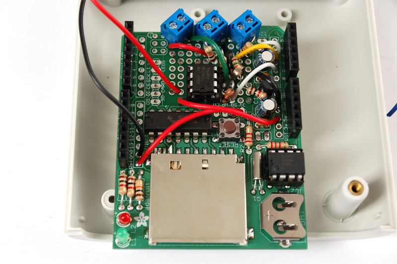
我將從準備案件開始。對于底部,將部件咬合起來以覆蓋兩個孔。
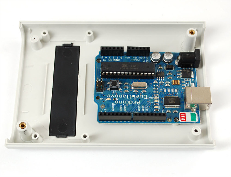
放置Arduino,使其與安裝孔對齊。
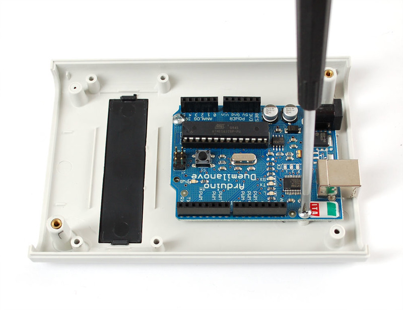
附加!使用兩個螺釘,第三個螺釘不合適,因為Arduino鉆頭太小。
LCD
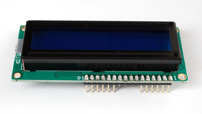
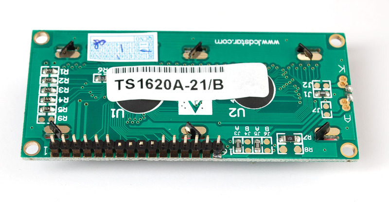
從包裝中取出LCD。您將需要某種10K電位器。我們將使用一些插頭和高級插座跳線,但您可以跳過該部分而僅焊接直接導線。

將標頭焊接進去,然后裁剪未使用的數(shù)據(jù)引腳以避免混淆。
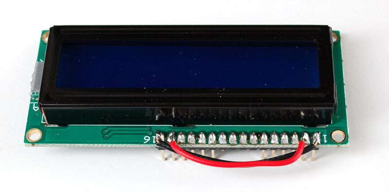
將LED背光燈線連接到LCD邏輯電源線。
接地RW引腳(未使用)。
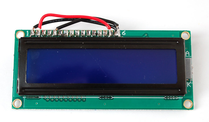
并除去該引腳以及引腳#1和#2(它們靠近安裝柱,因此我們將進行連接而不是針腳#15和#16)。
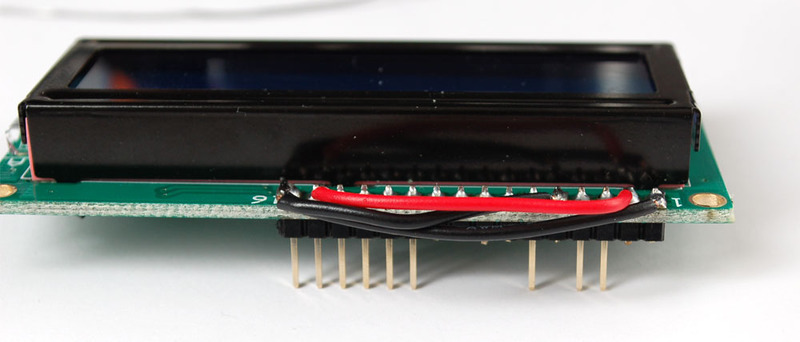
將10K電位器連接到5V,引腳3和接地。
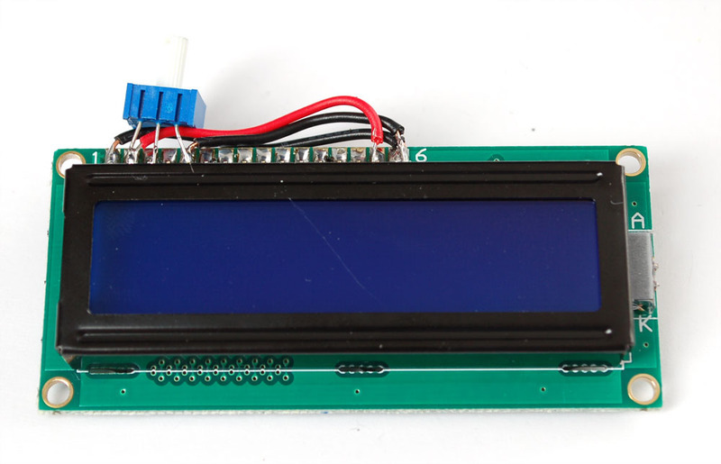
和固定銷3。
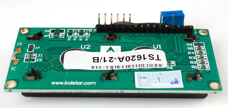
現(xiàn)在,我們有從左到右使用的8個引腳:接地,電源,D7至D4,RS和EN。連接套接字。
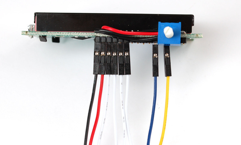
并剪裁
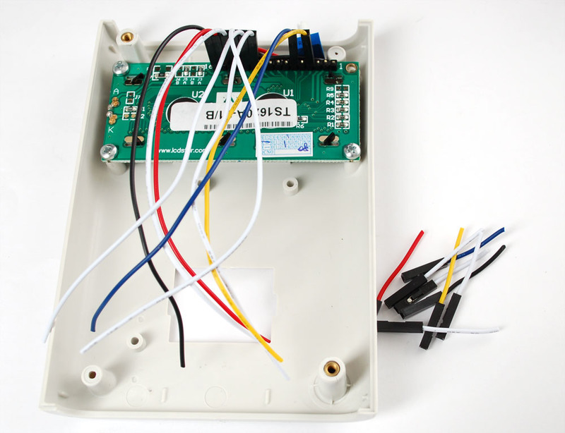
LCD連接和測試
從接通電源開始,紅色變?yōu)? 5V,黑色變?yōu)榻拥亍T贚CD教程中執(zhí)行測試以驗證對比度電位計是否正常工作。
這樣連接其余電線:
EN→數(shù)字#2
RS→數(shù)字#3
D4→數(shù)字#4
D5→數(shù)字#5
D6→數(shù)字#6
D7→數(shù)字#7
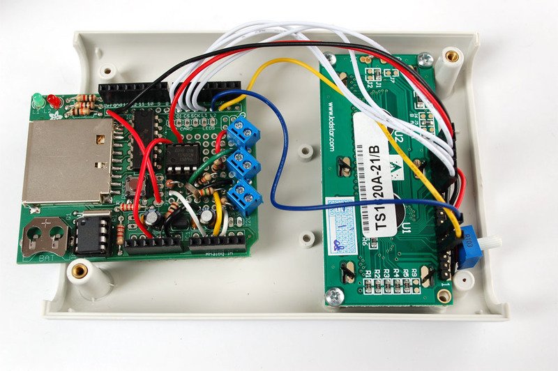
然后嘗試通過上傳草圖將其顯示出來。即使它什么也不顯示,您也應該使LCD正常工作。


下載:Project Zip 或 solartrack.ino | 在Github上查看
復制代碼
/*
Portable solar panel efficiency tracker. For testing out solar panels!
See https://learn.adafruit.com/portable-solar-charging-tracker for more information
Code is public domain, MIT License by Limor “Ladyada” Fried
*/
// include the library code:
#include
#include
// initialize the library with the numbers of the interface pins
LiquidCrystal lcd(2, 3, 4, 5, 6, 7 );
#define aref_voltage 3.3 // we tie 3.3V to ARef and measure it with a multimeter!
int lipoPin = 3; // the battery
float lipoMult = 1.666; // how much to multiply to get the original voltage
int PVPin = 2; // the cell
float PVMult = 2; // how much to multiply to get the original voltage
int currentPin = 1;
float currentMult = 208; // how much to multiply to get the original current draw
void setup(void) {
// We‘ll send debugging information via the Serial monitor
Serial.begin(9600);
// set up the LCD’s number of rows and columns:
lcd.begin(16, 2);
lcd.clear();
// Print a message to the LCD.
lcd.print(“Solar logger”);
delay(2000);
lcd.clear();
// If you want to set the aref to something other than 5v
analogReference(EXTERNAL);
byte delta[8] = {
B00000,
B00100,
B00100,
B01010,
B01010,
B10001,
B11111,
B00000
};
lcd.createChar(0, delta);
}
void loop(void) {
adcreading = analogRead(lipoPin);
Serial.println(adcreading);
float lipoV = adcreading;
lipoV *= aref_voltage;
lipoV /= 1024;
lipoV *= lipoMult;
lcd.clear();
Serial.print(“LiPo voltage = ”);
Serial.println(lipoV); // the raw analog reading
lcd.setCursor(0, 0);
lcd.print(“LiPo=”);
lcd.print(lipoV);
lcd.print(‘ ’);
lcd.write((uint8_t)0);
adcreading = analogRead(PVPin);
float PVV = adcreading;
PVV *= aref_voltage;
PVV /= 1024;
PVV *= PVMult;
lcd.print((int)((PVV-lipoV) * 1000), DEC); // in mV
lcd.print(“mV”);
Serial.print(“PV voltage = ”);
Serial.println(PVV); // the raw analog reading
lcd.setCursor(0, 1);
lcd.print(“PV=”);
lcd.print(PVV);
adcreading = analogRead(currentPin);
float currentI = adcreading;
currentI *= aref_voltage;
currentI /= 1024;
currentI *= currentMult;
Serial.print(“Current (mA) = ”);
Serial.println(currentI); // the raw analog reading
lcd.print(“ I=”);
lcd.print((int)currentI);
lcd.print(“mA”);
delay(1000);
}
/*
Portable solar panel efficiency tracker. For testing out solar panels!
See https://learn.adafruit.com/portable-solar-charging-tracker for more information
Code is public domain, MIT License by Limor “Ladyada” Fried
*/
// include the library code:
#include
#include
// initialize the library with the numbers of the interface pins
LiquidCrystal lcd(2, 3, 4, 5, 6, 7 );
#define aref_voltage 3.3 // we tie 3.3V to ARef and measure it with a multimeter!
int lipoPin = 3; // the battery
float lipoMult = 1.666; // how much to multiply to get the original voltage
int PVPin = 2; // the cell
float PVMult = 2; // how much to multiply to get the original voltage
int currentPin = 1;
float currentMult = 208; // how much to multiply to get the original current draw
void setup(void) {
// We‘ll send debugging information via the Serial monitor
Serial.begin(9600);
// set up the LCD’s number of rows and columns:
lcd.begin(16, 2);
lcd.clear();
// Print a message to the LCD.
lcd.print(“Solar logger”);
delay(2000);
lcd.clear();
// If you want to set the aref to something other than 5v
analogReference(EXTERNAL);
byte delta[8] = {
B00000,
B00100,
B00100,
B01010,
B01010,
B10001,
B11111,
B00000
};
lcd.createChar(0, delta);
}
void loop(void) {
int adcreading;
adcreading = analogRead(lipoPin);
Serial.println(adcreading);
float lipoV = adcreading;
lipoV *= aref_voltage;
lipoV /= 1024;
lipoV *= lipoMult;
lcd.clear();
Serial.print(“LiPo voltage = ”);
Serial.println(lipoV); // the raw analog reading
lcd.setCursor(0, 0);
lcd.print(“LiPo=”);
lcd.print(lipoV);
lcd.print(‘ ’);
lcd.write((uint8_t)0);
adcreading = analogRead(PVPin);
float PVV = adcreading;
PVV *= aref_voltage;
PVV /= 1024;
PVV *= PVMult;
lcd.print((int)((PVV-lipoV) * 1000), DEC); // in mV
lcd.print(“mV”);
Serial.print(“PV voltage = ”);
Serial.println(PVV); // the raw analog reading
lcd.setCursor(0, 1);
lcd.print(“PV=”);
lcd.print(PVV);
adcreading = analogRead(currentPin);
float currentI = adcreading;
currentI *= aref_voltage;
currentI /= 1024;
currentI *= currentMult;
Serial.print(“Current (mA) = ”);
Serial.println(currentI); // the raw analog reading
lcd.print(“ I=”);
lcd.print((int)currentI);
lcd.print(“mA”);
delay(1000);
}
現(xiàn)在可以連接外部面板和電池等。接線端子還可以,但不是很優(yōu)雅。相反,我將使用可插拔連接器。音頻連接器在這里可以很好地工作,每個連接只需要2個引腳(接地和信號),因此3.5毫米單聲道耳機插頭和插孔是一種廉價且易于獲得的解決方案。一定要獲得面板安裝插孔!
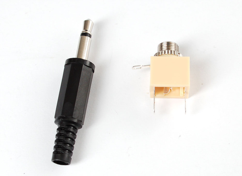
從連接充電器輸出的JST電纜開始(以測量脂質)。松開插頭,穿過電線,然后將每個引腳焊接到壓接處。通常,您應始終使“套管”或“環(huán)”接地,并向“尖端”發(fā)出正信號。保持事物易于跟蹤!
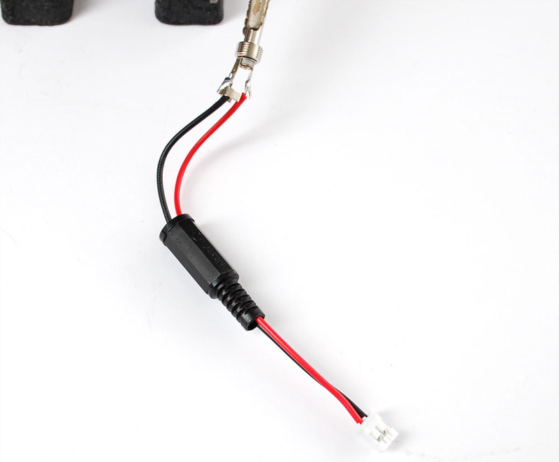
壓接,確保不使電線短路。這可能有點挑戰(zhàn),因此請使用萬用表進行測試!
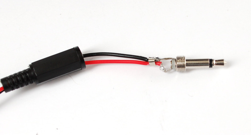
下一步,剝去miniB usb電纜,并拔出紅色和黑色電線。我們還使用一些熱縮來保護電纜的末端。
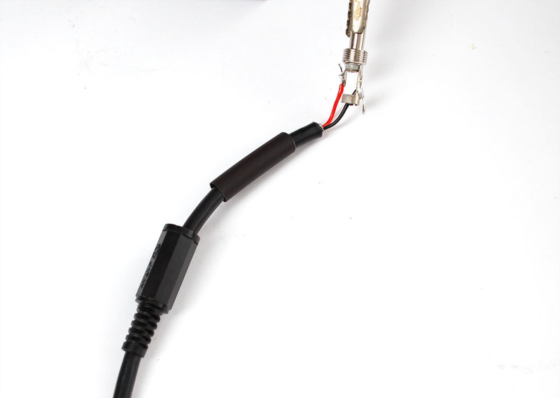
壓接
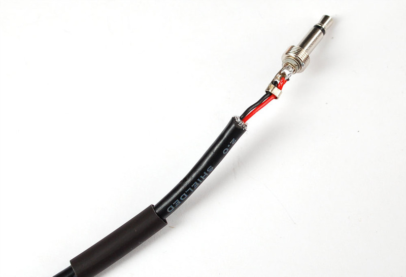
熱縮!
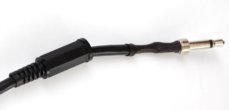
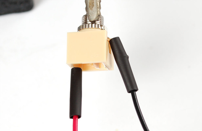
接下來是千斤頂。如圖所示,將任何絞合線連接到套管和末端連接。
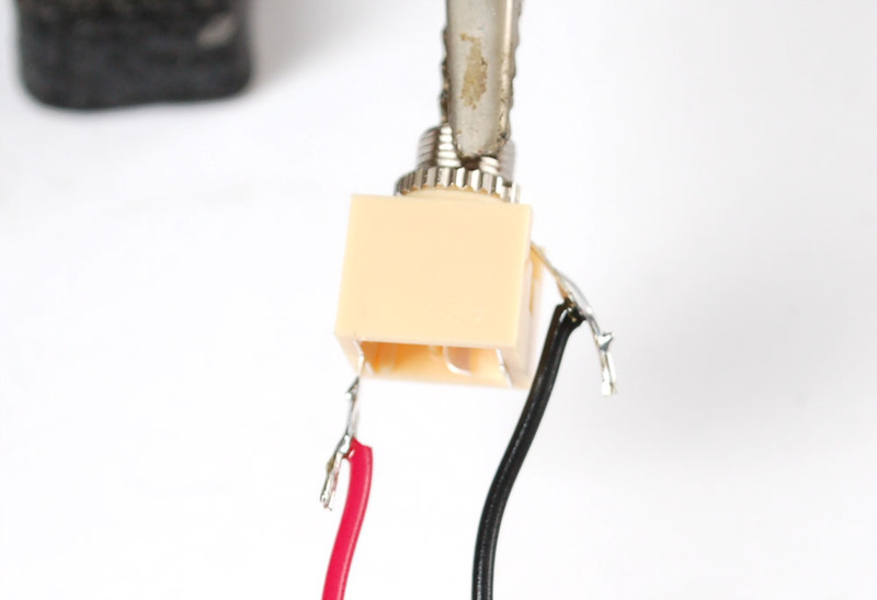
我們喜歡熱收縮!
將插孔連接到端子塊。
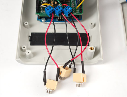
在完成所有步驟之前,現(xiàn)在是測試的好時機!確認從面板和鋰聚合物電池獲得了合理的電壓。如果您可以靠近窗戶,請查看是否可以給電池充電。
完成
當然,我們希望將面板安裝插孔安裝在面板上。抓住盒子的末端。它是由ABS制成的。
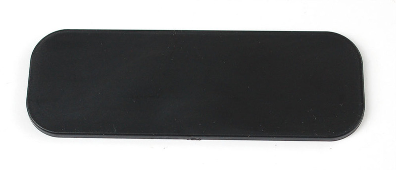
意味著它們非常容易鉆孔或加工!
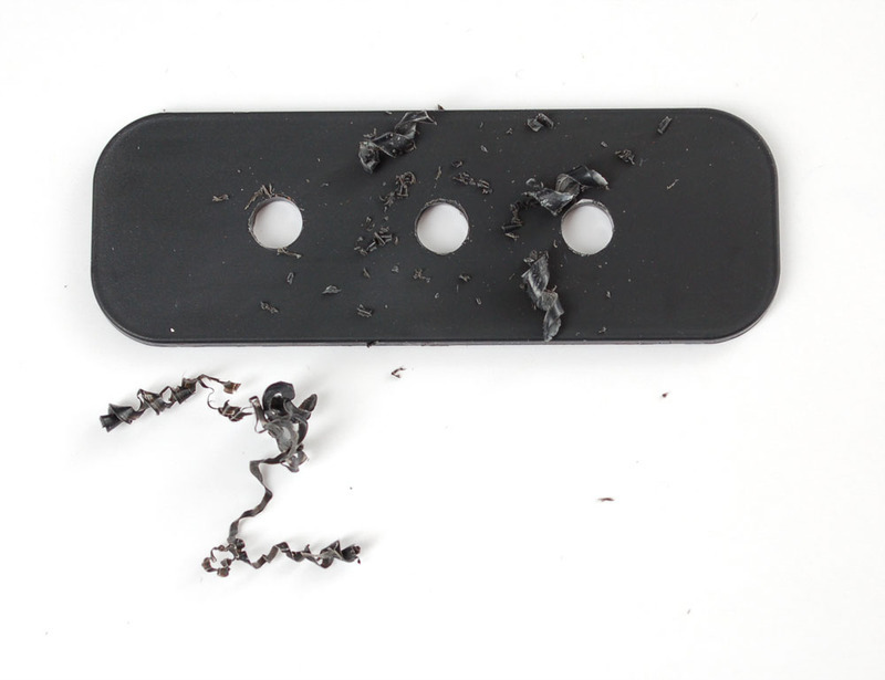
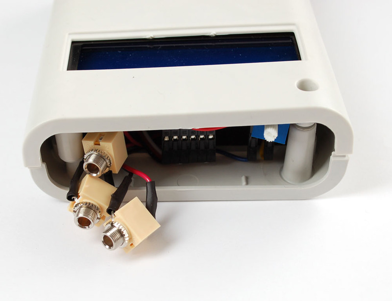
我們有一個標簽制造商,所以我們做了漂亮的小標簽!
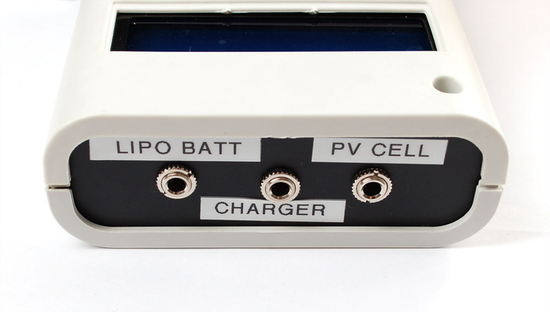
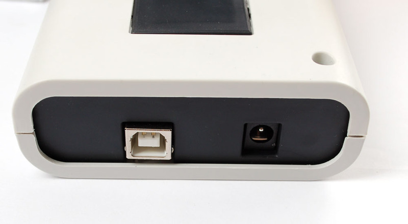
另一個一側獲得了覆蓋Arduino電源和編程插槽的預切盒。
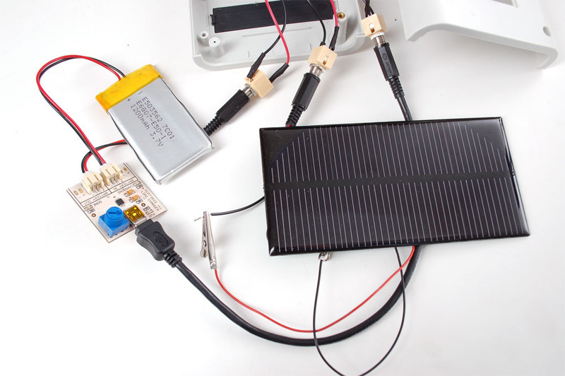
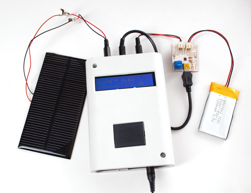
準備出發(fā)!在這里,我展示了如何通過連接鱷魚皮來嘗試不同的面板。脂質輸入來自充電器上的直通連接。當面板為電池充電時,我可以跟蹤電壓和電流。
責任編輯:wv
-
太陽能
+關注
關注
37文章
3433瀏覽量
114444 -
追蹤器
+關注
關注
0文章
171瀏覽量
25746
發(fā)布評論請先 登錄
相關推薦
便攜式儲能已經(jīng)實現(xiàn)全國產(chǎn)了嗎?
便攜式示波器的技術原理和應用場景
實現(xiàn)高效供電,PMU成便攜式儲能中的關鍵
GoSun推出電動汽車太陽能充電盒
太陽能組件el測試儀的便攜款版本有哪些特點?
太陽能板與太陽能發(fā)電機有什么不同
太陽能充電器的原理圖
太陽能光伏組件是什么?太陽能光伏組件生產(chǎn)流程
太陽能充電器電路圖分享


 便攜式太陽能充電追蹤器的制作



評論