通常,LM35溫度傳感器與微控制器一起使用以測(cè)量溫度,因?yàn)樗阋饲乙子讷@得。但是 LM35 給出了模擬值,我們需要使用 ADC(模數(shù)轉(zhuǎn)換器)將它們轉(zhuǎn)換為數(shù)字值。但今天我們使用DS18B20溫度傳感器,不需要ADC轉(zhuǎn)換即可獲得溫度。在這里,我們將使用帶有DS18B20的PIC微控制器來(lái)測(cè)量溫度。
因此,在這里,我們使用微芯片的PIC16F877A微控制器單元構(gòu)建具有以下規(guī)格的溫度計(jì)。
它將顯示從 -55 度到 +125 度的全溫度范圍。
僅當(dāng)溫度變化 + / - .2 度時(shí),它才會(huì)顯示溫度。
所需組件:-
Pic16F877A – PDIP40 封裝
面包板
皮基特-3
5V 適配器
液晶顯示器 JHD162A
DS18b20 溫度傳感器
用于連接外圍設(shè)備的電線。
4.7k 電阻器 – 2 個(gè)
10k鍋
20mHz 晶體
2 個(gè) 33pF 陶瓷電容器
DS18B20溫度傳感器:
DS18B20是一款出色的傳感器,可準(zhǔn)確檢測(cè)溫度。該傳感器提供 9 位至 12 位的溫度檢測(cè)分辨率。該傳感器僅與一根導(dǎo)線通信,不需要任何ADC即可獲取模擬溫度并將其轉(zhuǎn)換為數(shù)字溫度。
傳感器的規(guī)格是:-
測(cè)量溫度范圍為 -55°C 至 +125°C(-67°F 至 +257°F)
-10°C 至 +85°C 范圍內(nèi)精度為 ±0.5°C
可編程分辨率從 9 位到 12 位
無(wú)需外部組件
傳感器采用1-Wire?接口
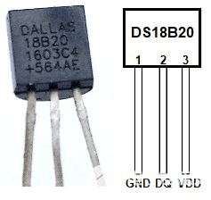
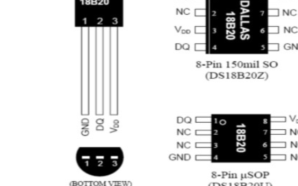
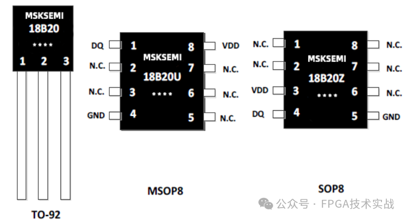
如果我們查看數(shù)據(jù)表中的上述引腳排列圖像,我們可以看到傳感器看起來(lái)與 BC547 或 BC557 封裝 TO-92 完全相同。第一個(gè)引腳是接地,第二個(gè)引腳是DQ或數(shù)據(jù),第三個(gè)引腳是VCC。
以下是數(shù)據(jù)表中的電氣規(guī)格,這是我們?cè)O(shè)計(jì)所需的。傳感器的額定電源電壓為+3.0V至+5.5V。它還需要上拉電源電壓,該電壓與上述電源電壓相同。

此外,對(duì)于 -10 攝氏度到 +10 攝氏度的范圍,精度裕度為 +-0.5 攝氏度,全范圍裕度的精度會(huì)發(fā)生變化,對(duì)于 -55 度到 +125 度范圍,精度裕度為 +-2 度。
如果我們?cè)俅尾榭磾?shù)據(jù)表,我們將看到傳感器的連接規(guī)格。我們可以在需要兩根電線(DATA 和 GND)的寄生電源模式下連接傳感器,或者可以使用外部電源連接傳感器,其中需要三根單獨(dú)的電線。我們將使用第二種配置。
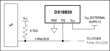
由于我們現(xiàn)在熟悉傳感器和連接相關(guān)區(qū)域的額定功率,我們現(xiàn)在可以專注于制作原理圖。
電路圖:-
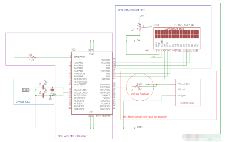
如果我們看到電路圖,我們將看到:-
16x2字符LCD通過(guò)PIC16F877A微控制器連接,其中RB0,RB1,RB2連接到LCD引腳RS,R/W和E。RB4、RB5、RB6 和 RB7 通過(guò) LCD 的 4 針 D4、D5、D6、D7 連接。液晶屏以4位模式或半字節(jié)模式連接。
一個(gè) 20MHz 晶體振蕩器和兩個(gè) 33pF 陶瓷電容器連接在 OSC1 和 OSC2 引腳上。它將為微控制器提供恒定的20Mhz時(shí)鐘頻率。
DS18B20也按照引腳配置連接,如前所述,采用4.7k上拉電阻連接。我已經(jīng)在面包板上連接了所有這些。
如果您不熟悉 PIC 微控制器,請(qǐng)按照我們的 PIC 微控制器教程進(jìn)行操作,說(shuō)明 PIC 微控制器入門(mén)。
步驟或代碼流:-
設(shè)置微控制器的配置,包括振蕩器配置。
使用ds18b20傳感器的每個(gè)周期都以復(fù)位開(kāi)始,因此我們將復(fù)位ds18b20并等待存在脈沖。
編寫(xiě)暫存器并將傳感器的分辨率設(shè)置為 12 位。
跳過(guò)ROM讀取,然后跳過(guò)復(fù)位脈沖。
提交轉(zhuǎn)換溫度命令。
從暫存器讀取溫度。
檢查溫度值是負(fù)值還是正值。
在 16x2 LCD 上打印溫度。
等待溫度變化 +/-.20 攝氏度。

代碼說(shuō)明:
本教程末尾提供了此數(shù)字溫度計(jì)的完整代碼,并附有演示視頻。您將需要一些頭文件來(lái)運(yùn)行該程序,可以從此處下載。
首先,我們需要在 pic 微控制器中設(shè)置配置位,然后從 void main 函數(shù)開(kāi)始。
然后下面四行用于包括庫(kù)頭文件,lcd.h和ds18b20.h。 xc.h 用于微控制器頭文件。
#include
#include
#include "supporting c files/ds18b20.h"
#include "supporting c files/lcd.h"
這些定義用于向溫度傳感器發(fā)送命令。這些命令列在傳感器的數(shù)據(jù)表中。
#define skip_rom 0xCC
#define convert_temp 0x44
#define write_scratchpad 0x4E
#define resolution_12bit 0x7F
#define read_scratchpad 0xBE
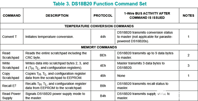
傳感器數(shù)據(jù)表中的表 3 顯示了使用宏發(fā)送相應(yīng)命令的所有命令。
僅當(dāng)溫度變化 +/- .20 度時(shí),溫度才會(huì)顯示在屏幕上。我們可以從這個(gè)temp_gap宏觀上改變這個(gè)溫差。通過(guò)更改此宏中的值,規(guī)范將更改。
另外兩個(gè)浮點(diǎn)變量用于存儲(chǔ)顯示的溫度數(shù)據(jù),并用溫差區(qū)分它們
#define temp_gap 20
float pre_val=0, aft_val=0;
.
在void main()函數(shù)中,lcd_init();是一個(gè)初始化LCD的函數(shù)。此 lcd_init() 函數(shù)是從 lcd.h 庫(kù)中調(diào)用的。
TRIS 寄存器用于選擇 I/O 引腳作為輸入或輸出。兩個(gè)無(wú)符號(hào)短變量 TempL 和 TempH 用于存儲(chǔ)來(lái)自溫度傳感器的 12 位分辨率數(shù)據(jù)。
void main(void) {
TRISD = 0xFF;
TRISA = 0x00;
TRISB = 0x00;
//TRISDbits_t.TRISD6 = 1;
unsigned short TempL, TempH;
unsigned int t, t2;
float difference1=0, difference2=0;
lcd_init();
讓我們看看 while 循環(huán),這里我們將 while(1) 循環(huán)分解成小塊。
這些線用于檢測(cè)溫度傳感器是否連接。
while(ow_reset()){
lcd_com(0x80);
lcd_puts ("Please Connect ");
lcd_com (0xC0);
lcd_puts("Temp-Sense Probe");
}
通過(guò)使用這段代碼,我們初始化傳感器并發(fā)送命令來(lái)轉(zhuǎn)換溫度。
lcd_puts (" ");
ow_reset();
write_byte(write_scratchpad);
write_byte(0);
write_byte(0);
write_byte(resolution_12bit); // 12bit resolution
ow_reset();
write_byte(skip_rom);
write_byte(convert_temp);
此代碼用于將 12 位溫度數(shù)據(jù)存儲(chǔ)在兩個(gè)無(wú)符號(hào)短變量中。
while (read_byte()==0xff);
__delay_ms(500);
ow_reset();
write_byte(skip_rom);
write_byte(read_scratchpad);
TempL = read_byte();
TempH = read_byte();
然后,如果您檢查下面的完整代碼,我們將創(chuàng)建if-else條件來(lái)找出溫度符號(hào)是正數(shù)還是負(fù)數(shù)。
通過(guò)使用 If 語(yǔ)句代碼,我們操作數(shù)據(jù)并查看溫度是否為負(fù),并確定溫度變化是否在 +/- .20 度范圍內(nèi)。在其他地方,我們檢查溫度是否為正和溫度變化檢測(cè)。
從DS18B20溫度傳感器獲取數(shù)據(jù):
讓我們看看1-Wire?接口的時(shí)差。我們正在使用20Mhz晶體。如果我們查看 ds18b20.c 文件,我們會(huì)看到
#define _XTAL_FREQ 20000000
此定義用于 XC8 編譯器延遲例程。20Mhz設(shè)置為晶體頻率。
我們制作了五個(gè)功能
ow_reset
read_bit
read_byte
write_bit
write_byte
1-Wire協(xié)議需要嚴(yán)格的時(shí)序相關(guān)插槽進(jìn)行通信。在數(shù)據(jù)表中,我們將獲得完美的時(shí)隙相關(guān)信息。?

在下面的函數(shù)中,我們創(chuàng)建了確切的時(shí)間段。為保持和釋放創(chuàng)建確切的延遲并控制相應(yīng)傳感器端口的TRIS位非常重要。
unsigned char ow_reset(void)
{
DQ_TRIS = 0; // Tris = 0 (output)
DQ = 0; // set pin# to low (0)
__delay_us(480); // 1 wire require time delay
DQ_TRIS = 1; // Tris = 1 (input)
__delay_us(60); // 1 wire require time delay
if (DQ == 0) // if there is a presence pluse
{
__delay_us(480);
return 0; // return 0 ( 1-wire is presence)
}
else
{
__delay_us(480);
return 1; // return 1 ( 1-wire is NOT presence)
}
} // 0=presence, 1 = no part
現(xiàn)在,根據(jù)以下讀取和寫(xiě)入中使用的時(shí)隙描述,我們分別創(chuàng)建了讀取和寫(xiě)入函數(shù)。
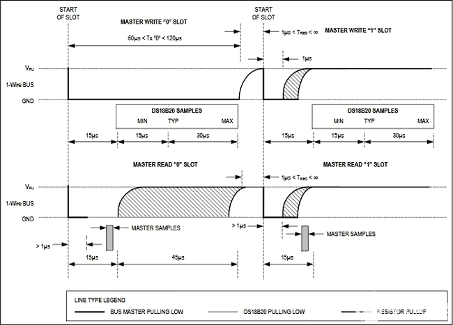
unsigned char read_bit(void)
{
unsigned char i;
DQ_TRIS = 1;
DQ = 0; // pull DQ low to start timeslot
DQ_TRIS = 1;
DQ = 1; // then return high
for (i=0; i<3; i++); // delay 15us from start of timeslot
return(DQ); // return value of DQ line
}
void write_bit(char bitval)
{
DQ_TRIS = 0;
DQ = 0; // pull DQ low to start timeslot
if(bitval==1) DQ =1; // return DQ high if write 1
__delay_us(5); // hold value for remainder of timeslot
DQ_TRIS = 1;
DQ = 1;
}// Delay provides 16us per loop, plus 24us. Therefore delay(5) = 104us
這就是我們?nèi)绾卫肈S18B20傳感器通過(guò)PIC微控制器獲得溫度。
/*
* File: main.c
* Author: Sourav Gupta
*
* Created on 11 April 2018, 17:57
*/
/*
* Configuration Related settings. Specific for microcontroller unit.
*/
#pragma config FOSC = HS // Oscillator Selection bits (HS oscillator)
#pragma config WDTE = OFF // Watchdog Timer Enable bit (WDT disabled)
#pragma config PWRTE = OFF // Power-up Timer Enable bit (PWRT disabled)
#pragma config BOREN = ON // Brown-out Reset Enable bit (BOR enabled)
#pragma config LVP = OFF // Low-Voltage (Single-Supply) In-Circuit Serial Programming Enable bit (RB3/PGM pin has PGM function; low-voltage programming enabled)
#pragma config CPD = OFF // Data EEPROM Memory Code Protection bit (Data EEPROM code protection off)
#pragma config WRT = OFF // Flash Program Memory Write Enable bits (Write protection off; all program memory may be written to by EECON control)
#pragma config CP = OFF // Flash Program Memory Code Protection bit (Code protection off)
#define _XTAL_FREQ 20000000
/*
* System Header files inclusions
*/
#include
#include
#include "supporting c files/ds18b20.h"
#include "supporting c files/lcd.h"
/*
* Ds18b20 related definition
*/
#define skip_rom 0xCC
#define convert_temp 0x44
#define write_scratchpad 0x4E
#define resolution_12bit 0x7F
#define read_scratchpad 0xBE
/*
* User interface related definitions
*/
#define temp_gap 20
float pre_val=0, aft_val=0;
/*
* Program flow related functions
*/
void sw_delayms(unsigned int d);
/* Main function / single Thread*/
void main(void) {
TRISD = 0xFF;
TRISA = 0x00;
TRISB = 0x00;
//TRISDbits_t.TRISD6 = 1;
unsigned short TempL, TempH;
unsigned int t, t2;
float difference1=0, difference2=0;
lcd_init();
while(1){
float i=0;
/* This is for presence detection of temp-sensing probe*/
while(ow_reset()){
lcd_com(0x80);
lcd_puts ("Please Connect ");
lcd_com (0xC0);
lcd_puts("Temp-Sense Probe");
}
/*------------------------------------------------------*/
lcd_puts (" ");
ow_reset();
write_byte(write_scratchpad);
write_byte(0);
write_byte(0);
write_byte(resolution_12bit); // 12bit resolution
ow_reset();
write_byte(skip_rom);
write_byte(convert_temp);
while (read_byte()==0xff);
__delay_ms(500);
ow_reset();
write_byte(skip_rom);
write_byte(read_scratchpad);
TempL = read_byte();
TempH = read_byte();
/*This is for Negative temperature*/
/*If result (TempH [Bitwise and] 1000 0000) = not 0
*then this condition get true.
case1. -0.5 degree value = 1111 1111. [1111 1111 & 1000 0000 = 1000 0000 which is not 0.]
case2. -55 degree value = 1111 1100. [1111 1100 & 1000 0000 = 1000 0000 which is not 0]
0x80 = 1000 0000
Test Case -10.125 output 1111 1111 0101 1110*/
if((TempH & 0x80)!=0){ // If condition will execute as TempH = 1111 1111 & 1000 0000 = 1000 0000.
t=TempH;// Store tempH value in t = 1111 1111 .
t<<=8;//after bitwise left shift 8 times value in t will be 1111 1111 0000 0000. ??
t=t|TempL;// t = 1111 1111 0000 0000 | 0101 1110 [ result t = 1111 1111 0101 1110]
t=t-1;//t = t-1 in this case t = 1111 1111 0101 1101.
t=~t;// t = 0000 0000 1010 0010.
t>>=4;// t = 0000 0000 0000 1010.
t=t*100;// t = 10 * 100 = 1000.
t2=TempL; //Store tempL value = 0101 1110.
t2=t2-1;// t2= 0101 1101
t2=~t2;//t2 = 1010 0010
t2=t2&0x0f;// t2 = 1010 0010 | 0000 1111 = 0000 0010
t2=t2 * 6.25; // 0000 00010 = 2 x 6.25 = 12.50
i=((unsigned int)t ) + (unsigned int)t2; //put both value in one variable 1000 + 12.5 = 1012.5
/*This if-else condition done because LCD would not refresh till temperature change -.20 or +.20 degree*/
pre_val=aft_val;
difference1 = pre_val - i;
difference2 = i - pre_val;
if(difference1 > temp_gap || difference2 > temp_gap){
aft_val = i;
lcd_com (0x80);
lcd_puts ("Circuit Digest");
lcd_com (0xc0);
lcd_puts("-");
lcd_bcd (5,aft_val);
lcd_data(223);
lcd_puts("C ");
}
else{
lcd_com (0x80);
lcd_puts ("Circuit Digest");
lcd_com (0xc0);
lcd_puts("-");
lcd_bcd (5,pre_val);
lcd_data(223);
lcd_puts("C ");
}
}
/*This is for positive Temperature*/
else {
i=((unsigned int)TempH << 8 ) + (unsigned int)TempL; //put both value in one variable?
i = i * 6.25; //calculations used from the table provided in the data sheet of ds18b20
/*This if-else condition done because LCD would not refresh till temperature change -.20 or +.20 degree*/
pre_val=aft_val;
difference1 = pre_val - i;
difference2 = i - pre_val;
if(difference1 > temp_gap || difference2 > temp_gap){
aft_val = i;
lcd_com (0x80);
lcd_puts ("Circuit Digest");
lcd_com (0xc0);
lcd_bcd (5,aft_val);
lcd_data(223);
lcd_puts("C ");
}
else{
lcd_com (0x80);
lcd_puts ("Circuit Digest");
lcd_com (0xc0);
lcd_bcd (5,pre_val);
lcd_data(223);
lcd_puts("C ");
}
}
}
return;
}
void sw_delayms(unsigned int d){
int x, y;
for(x=0;x
for(y=0;y<=1275;y++);?
}
-
溫度傳感器
+關(guān)注
關(guān)注
48文章
2940瀏覽量
156020 -
adc
+關(guān)注
關(guān)注
98文章
6495瀏覽量
544467 -
PIC
+關(guān)注
關(guān)注
8文章
507瀏覽量
87540 -
DS18B20
+關(guān)注
關(guān)注
10文章
779瀏覽量
80824
發(fā)布評(píng)論請(qǐng)先 登錄
相關(guān)推薦
基于STM32的DS18B20溫度傳感器設(shè)計(jì)
DS18B20溫度傳感器是什么
DS18B20數(shù)字溫度傳感器概述
利用數(shù)字溫度傳感器DS18B20測(cè)量溫度信號(hào)
數(shù)字溫度傳感器DS18B20的設(shè)計(jì)及應(yīng)用
基于ARM和DS18B20的溫度監(jiān)測(cè)系統(tǒng)
DS18B20數(shù)字溫度傳感器
智能溫度傳感器DS18B20的原理與應(yīng)用
ds18b20的特性_ds18b20溫度傳感器應(yīng)用
ds18b20溫度傳感器和dht11的區(qū)別
ds18b20溫度傳感器如何使用
ds18b20溫度傳感器怎么接線
ds18b20傳感器的使用方法
DS18B20溫度傳感器的工作原理和硬件設(shè)計(jì)


 如何利用DS18B20傳感器通過(guò)PIC微控制器獲得溫度


評(píng)論