本文來源電子發燒友社區,作者:性感的· , 帖子地址:https://bbs.elecfans.com/jishu_2286218_1_1.html
泰凌微的代碼結構和Nrf52832的芯片代碼差異性還是比較大的,很多代碼define go to 你會發現是庫,看不到底層代碼了。經過一番學習后,總結幾點共大家借鑒吧。對初學藍牙的朋友還是有些幫助的,如果大神,就請直接劃走吧。
BLE的設置大多都在app_att.c和app_att.h里面。
比如更改名字 在這個數組里更改 static const u8 my_devName[] = {'e','S','a','m','p','l','e'};
后面有函數會調用my_devName,這個數組
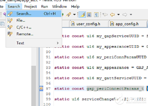
更改最大最小廣播時間等參數my_periConnParameters 。同理,相比Nrf52832的代碼來說,這并不是宏定義出來,大多數參數都是用結構體,或者數組來設置。Search,注意不要用Ctrl+F,使用Keil的朋友習慣了這個,Ctrl+F是只能在文件搜索的,無法在工程內搜索。
基本這些藍牙設置的參數,更改UUID UI,服務的添加,屬性更改的東西都可以找到

快速go to define 的快捷鍵是Ctrl+鼠標左鍵。
下面來講一下app的設置
復制代碼
基礎的官網的demo基本在這里,可以通過宏定義在屏蔽或開啟編譯,具體的事件是如何調度的,通過仿真也是非常容易理解了。到了這里,基本使用這款芯片完成底層驅動都沒問題的。希望Telink的名氣越來越大,以后更多產品都用到Telink的芯片吧。為國產芯片點贊。
泰凌微的代碼結構和Nrf52832的芯片代碼差異性還是比較大的,很多代碼define go to 你會發現是庫,看不到底層代碼了。經過一番學習后,總結幾點共大家借鑒吧。對初學藍牙的朋友還是有些幫助的,如果大神,就請直接劃走吧。
BLE的設置大多都在app_att.c和app_att.h里面。
比如更改名字 在這個數組里更改 static const u8 my_devName[] = {'e','S','a','m','p','l','e'};
后面有函數會調用my_devName,這個數組
更改最大最小廣播時間等參數my_periConnParameters 。同理,相比Nrf52832的代碼來說,這并不是宏定義出來,大多數參數都是用結構體,或者數組來設置。Search,注意不要用Ctrl+F,使用Keil的朋友習慣了這個,Ctrl+F是只能在文件搜索的,無法在工程內搜索。
基本這些藍牙設置的參數,更改UUID UI,服務的添加,屬性更改的東西都可以找到

快速go to define 的快捷鍵是Ctrl+鼠標左鍵。
下面來講一下app的設置
- /********************************************************************************************************
- * @file app_config.h
- *
- * @brief This is the header file for BLE SDK
- *
- * @author BLE GROUP
- * @date 2020.06
- *
- * [url=home.php?mod=space&uid=1930556]@par[/url] Copyright (c) 2020, Telink Semiconductor (Shanghai) Co., Ltd. ("TELINK")
- * All rights reserved.
- *
- * Redistribution and use in source and binary forms, with or without
- * modification, are permitted provided that the following conditions are met:
- *
- * 1. Redistributions of source code must retain the above copyright
- * notice, this list of conditions and the following disclaimer.
- *
- * 2. Unless for usage inside a TELINK integrated circuit, redistributions
- * in binary form must reproduce the above copyright notice, this list of
- * conditions and the following disclaimer in the documentation and/or other
- * materials provided with the distribution.
- *
- * 3. Neither the name of TELINK, nor the names of its contributors may be
- * used to endorse or promote products derived from this software without
- * specific prior written permission.
- *
- * 4. This software, with or without modification, must only be used with a
- * TELINK integrated circuit. All other usages are subject to written permission
- * from TELINK and different commercial license may apply.
- *
- * 5. Licensee shall be solely responsible for any claim to the extent arising out of or
- * relating to such deletion(s), modification(s) or alteration(s).
- *
- * THIS SOFTWARE IS PROVIDED BY THE COPYRIGHT HOLDERS AND CONTRIBUTORS "AS IS" AND
- * ANY EXPRESS OR IMPLIED WARRANTIES, INCLUDING, BUT NOT LIMITED TO, THE IMPLIED
- * WARRANTIES OF MERCHANTABILITY AND FITNESS FOR A PARTICULAR PURPOSE ARE
- * DISCLAIMED. IN NO EVENT SHALL COPYRIGHT HOLDER BE LIABLE FOR ANY
- * DIRECT, INDIRECT, INCIDENTAL, SPECIAL, EXEMPLARY, OR CONSEQUENTIAL DAMAGES
- * (INCLUDING, BUT NOT LIMITED TO, PROCUREMENT OF SUBSTITUTE GOODS OR SERVICES;
- * LOSS OF USE, DATA, OR PROFITS; OR BUSINESS INTERRUPTION) HOWEVER CAUSED AND
- * ON ANY THEORY OF LIABILITY, WHETHER IN CONTRACT, STRICT LIABILITY, OR TORT
- * (INCLUDING NEGLIGENCE OR OTHERWISE) ARISING IN ANY WAY OUT OF THE USE OF THIS
- * SOFTWARE, EVEN IF ADVISED OF THE POSSIBILITY OF SUCH DAMAGE.
- *
- *******************************************************************************************************/
- #pragma once
- /////////////////// FEATURE SELECT /////////////////////////////////
- /**
- *[url=home.php?mod=space&uid=2666770]@Brief[/url]Feature select in bLE Sample project
- */
- #define BLE_APP_PM_ENABLE 1
- #define PM_DEEPSLEEP_RETENTION_ENABLE 1
- #define TEST_CONN_CURRENT_ENABLE 0 //test connection current, disable UI to have a pure power
- #define APP_SECURITY_ENABLE 1
- #define APP_DIRECT_ADV_ENABLE 1
- #define BLE_OTA_SERVER_ENABLE 1
- #define BATT_CHECK_ENABLE 0
- /**
- *@briefflash firmware check
- */
- #define FLASH_FIRMWARE_CHECK_ENABLE 0
- /**
- *@brieffirmware signature check
- */
- #define FIRMWARES_SIGNATURE_ENABLE 0
- /**
- *@briefDEBUGConfiguration
- */
- #define UART_PRINT_DEBUG_ENABLE 0
- #define DEBUG_GPIO_ENABLE 0
- #define JTAG_DEBUG_DISABLE 0
- /**
- *@briefUI Configuration
- */
- #define UI_LED_ENABLE 1
- #define UI_BUTTON_ENABLE 0
- #if (TEST_CONN_CURRENT_ENABLE) //test current, disable keyboard
- #define UI_KEYBOARD_ENABLE 0
- #else
- #define UI_KEYBOARD_ENABLE 1
- #endif
- //SAMPLE SELECT EVK BOARD
- #if (UI_KEYBOARD_ENABLE) // if test pure power, kyeScan GPIO setting all disabled
- //---------------KeyMatrix PB2/PB3/PB4/PB5 -----------------------------
- #define MATRIX_ROW_PULL PM_PIN_PULLDOWN_100K
- #define MATRIX_COL_PULL PM_PIN_PULLUP_10K
- #define KB_LINE_HIGH_VALID 0 //dirve pin output 0 when keyscan, scanpin read 0 is valid
- #define CR_VOL_UP 0xf0////
- #define CR_VOL_DN 0xf1
- /**
- *@briefNormal keyboard map
- */
- #define KB_MAP_NORMAL { {CR_VOL_DN, VK_1},
- {CR_VOL_UP, VK_2}, }
- //////////////////// KEY CONFIG (EVK board) ///////////////////////////
- #defineKB_DRIVE_PINS{GPIO_PC2, GPIO_PC0}
- #defineKB_SCAN_PINS {GPIO_PC3, GPIO_PC1}
- //drive pin as gpio
- #define PC2_FUNC AS_GPIO
- #define PC0_FUNC AS_GPIO
- //drive pin need 100K pulldown
- #define PULL_WAKEUP_SRC_PC2 MATRIX_ROW_PULL
- #define PULL_WAKEUP_SRC_PC0 MATRIX_ROW_PULL
- //drive pin open input to read gpio wakeup level
- #define PC2_INPUT_ENABLE 1
- #define PC0_INPUT_ENABLE 1
- //scan pin as gpio
- #define PC3_FUNC AS_GPIO
- #define PC1_FUNC AS_GPIO
- //scanpin need 10K pullup
- #define PULL_WAKEUP_SRC_PC3 MATRIX_COL_PULL
- #define PULL_WAKEUP_SRC_PC1 MATRIX_COL_PULL
- //scan pin open input to read gpio level
- #define PC3_INPUT_ENABLE 1
- #define PC1_INPUT_ENABLE 1
- #if (UI_LED_ENABLE)
- /**
- *@briefDefinition gpio for led
- */
- #define GPIO_LED_WHITE GPIO_PB6
- #define GPIO_LED_GREEN GPIO_PB5
- #define GPIO_LED_BLUE GPIO_PB4
- #define GPIO_LED_RED GPIO_PB7
- #define LED_ON_LEVAL 1 //gpio output high voltage to turn on led
- #define PB7_FUNC AS_GPIO
- #define PB6_FUNC AS_GPIO
- #define PB5_FUNC AS_GPIO
- #define PB4_FUNC AS_GPIO
- #define PB7_OUTPUT_ENABLE 1
- #define PB6_OUTPUT_ENABLE 1
- #define PB5_OUTPUT_ENABLE 1
- #define PB4_OUTPUT_ENABLE 1
- #endif
- #elif (UI_BUTTON_ENABLE)
- //SAMPLE SELECT DONGLE BOARD
- #undefPM_DEEPSLEEP_RETENTION_ENABLE
- #define PM_DEEPSLEEP_RETENTION_ENABLE 0 //dongle demo no need deepSleepRetention
- //---------------Button -------------------------------
- /**
- *@briefDefinition gpio for button detection
- */
- #define SW1_GPIO GPIO_PB2
- #define SW2_GPIO GPIO_PB3
- #define PB2_FUNC AS_GPIO
- #define PB3_FUNC AS_GPIO
- #define PB2_INPUT_ENABLE 1
- #define PB3_INPUT_ENABLE 1
- #define PULL_WAKEUP_SRC_PB2 PM_PIN_PULLUP_10K
- #define PULL_WAKEUP_SRC_PB3 PM_PIN_PULLUP_10K
- #if (UI_LED_ENABLE)
- /**
- *@briefDefinition gpio for led
- */
- //---------------LED ----------------------------------
- #define GPIO_LED_RED GPIO_PB4
- #define GPIO_LED_WHITE GPIO_PB1
- #define GPIO_LED_GREEN GPIO_PB0
- #define GPIO_LED_BLUE GPIO_PB7
- #define GPIO_LED_YELLOW GPIO_PB5
- #define PB4_FUNC AS_GPIO
- #define PB1_FUNC AS_GPIO
- #define PB0_FUNC AS_GPIO
- #define PB7_FUNC AS_GPIO
- #define PB5_FUNC AS_GPIO
- #define PB4_OUTPUT_ENABLE 1
- #define PB1_OUTPUT_ENABLE 1
- #define PB0_OUTPUT_ENABLE 1
- #define PB7_OUTPUT_ENABLE 1
- #define PB5_OUTPUT_ENABLE 1
- #define LED_ON_LEVAL 1 //gpio output high voltage to turn on led
- #endif
- #endif
- /////////////////// DEEP SAVE FLG //////////////////////////////////
- #define USED_DEEP_ANA_REG DEEP_ANA_REG1 //u8,can save 8 bit info when deep
- #define LOW_BATT_FLG BIT(0) //if 1: low battery
- #define CONN_DEEP_FLG BIT(1) //if 1: conn deep, 0: adv deep
- #define IR_MODE_DEEP_FLG BIT(2) //if 1: IR mode, 0: BLE mode
- #define LOW_BATT_SUSPEND_FLG BIT(3) //if 1 : low battery, < 1.8v
- #if (BATT_CHECK_ENABLE)
- #define VBAT_CHANNEL_EN 0
- #if VBAT_CHANNEL_EN
- /** The battery voltage sample range is 1.8~3.5V **/
- #else
- /** if the battery voltage > 3.6V, should take some external voltage divider **/
- #define GPIO_BAT_DETECT GPIO_PB0
- #define PB0_FUNC AS_GPIO
- #define PB0_INPUT_ENABLE 0
- #define PB0_OUTPUT_ENABLE 0
- #define PB0_DATA_OUT 0
- #define ADC_INPUT_PIN_CHN ADC_GPIO_PB0
- #endif
- #endif
- #if (JTAG_DEBUG_DISABLE)//2-wire jtag mode
- #define PE6_FUNC AS_GPIO
- #define PE7_FUNC AS_GPIO
- #define PE6_INPUT_ENABLE 0
- #define PE7_INPUT_ENABLE 0
- #endif
- /////////////////////////////////////// PRINT DEBUG INFO ///////////////////////////////////////
- #if (UART_PRINT_DEBUG_ENABLE)
- //the baud rate should not bigger than 115200 when MCU clock is 16M)
- //the baud rate should not bigger than 1000000 when MCU clock is 24M)
- #define PRINT_BAUD_RATE 115200
- #define DEBUG_INFO_TX_PIN GPIO_PC6
- #define PULL_WAKEUP_SRC_PC6 PM_PIN_PULLUP_10K
- #define PC6_OUTPUT_ENABLE 1
- #define PC6_DATA_OUT 1 //must
- #endif
- /**
- *@briefDefinition for gpio debug
- */
- #if(DEBUG_GPIO_ENABLE)
- #define GPIO_CHN0 GPIO_PE1
- #define GPIO_CHN1 GPIO_PE2
- #define GPIO_CHN2 GPIO_PA0
- #define GPIO_CHN3 GPIO_PA4
- #define GPIO_CHN4 GPIO_PA3
- #define GPIO_CHN5 GPIO_PB0
- #define GPIO_CHN6 GPIO_PB2
- #define GPIO_CHN7 GPIO_PE0
- #define GPIO_CHN8 GPIO_PA2
- #define GPIO_CHN9 GPIO_PA1
- #define GPIO_CHN10 GPIO_PB1
- #define GPIO_CHN11 GPIO_PB3
- #define GPIO_CHN12 GPIO_PC7
- #define GPIO_CHN13 GPIO_PC6
- #define GPIO_CHN14 GPIO_PC5
- #define GPIO_CHN15 GPIO_PC4
- #define PE1_OUTPUT_ENABLE 1
- #define PE2_OUTPUT_ENABLE 1
- #define PA0_OUTPUT_ENABLE 1
- #define PA4_OUTPUT_ENABLE 1
- #define PA3_OUTPUT_ENABLE 1
- #define PB0_OUTPUT_ENABLE 1
- #define PB2_OUTPUT_ENABLE 1
- #define PE0_OUTPUT_ENABLE 1
- #define PA2_OUTPUT_ENABLE 1
- #define PA1_OUTPUT_ENABLE 1
- #define PB1_OUTPUT_ENABLE 1
- #define PB3_OUTPUT_ENABLE 1
- #define PC7_OUTPUT_ENABLE 1
- #define PC6_OUTPUT_ENABLE 1
- #define PC5_OUTPUT_ENABLE 1
- #define PC4_OUTPUT_ENABLE 1
- #define DBG_CHN0_LOW gpio_write(GPIO_CHN0, 0)
- #define DBG_CHN0_HIGH gpio_write(GPIO_CHN0, 1)
- #define DBG_CHN0_TOGGLE gpio_toggle(GPIO_CHN0)
- #define DBG_CHN1_LOW gpio_write(GPIO_CHN1, 0)
- #define DBG_CHN1_HIGH gpio_write(GPIO_CHN1, 1)
- #define DBG_CHN1_TOGGLE gpio_toggle(GPIO_CHN1)
- #define DBG_CHN2_LOW gpio_write(GPIO_CHN2, 0)
- #define DBG_CHN2_HIGH gpio_write(GPIO_CHN2, 1)
- #define DBG_CHN2_TOGGLE gpio_toggle(GPIO_CHN2)
- #define DBG_CHN3_LOW gpio_write(GPIO_CHN3, 0)
- #define DBG_CHN3_HIGH gpio_write(GPIO_CHN3, 1)
- #define DBG_CHN3_TOGGLE gpio_toggle(GPIO_CHN3)
- #define DBG_CHN4_LOW gpio_write(GPIO_CHN4, 0)
- #define DBG_CHN4_HIGH gpio_write(GPIO_CHN4, 1)
- #define DBG_CHN4_TOGGLE gpio_toggle(GPIO_CHN4)
- #define DBG_CHN5_LOW gpio_write(GPIO_CHN5, 0)
- #define DBG_CHN5_HIGH gpio_write(GPIO_CHN5, 1)
- #define DBG_CHN5_TOGGLE gpio_toggle(GPIO_CHN5)
- #define DBG_CHN6_LOW gpio_write(GPIO_CHN6, 0)
- #define DBG_CHN6_HIGH gpio_write(GPIO_CHN6, 1)
- #define DBG_CHN6_TOGGLE gpio_toggle(GPIO_CHN6)
- #define DBG_CHN7_LOW gpio_write(GPIO_CHN7, 0)
- #define DBG_CHN7_HIGH gpio_write(GPIO_CHN7, 1)
- #define DBG_CHN7_TOGGLE gpio_toggle(GPIO_CHN7)
- #define DBG_CHN8_LOW gpio_write(GPIO_CHN8, 0)
- #define DBG_CHN8_HIGH gpio_write(GPIO_CHN8, 1)
- #define DBG_CHN8_TOGGLE gpio_toggle(GPIO_CHN8)
- #define DBG_CHN9_LOW gpio_write(GPIO_CHN9, 0)
- #define DBG_CHN9_HIGH gpio_write(GPIO_CHN9, 1)
- #define DBG_CHN9_TOGGLE gpio_toggle(GPIO_CHN9)
- #define DBG_CHN10_LOW gpio_write(GPIO_CHN10, 0)
- #define DBG_CHN10_HIGH gpio_write(GPIO_CHN10, 1)
- #define DBG_CHN10_TOGGLE gpio_toggle(GPIO_CHN10)
- #define DBG_CHN11_LOW gpio_write(GPIO_CHN11, 0)
- #define DBG_CHN11_HIGH gpio_write(GPIO_CHN11, 1)
- #define DBG_CHN11_TOGGLE gpio_toggle(GPIO_CHN11)
- #define DBG_CHN12_LOW gpio_write(GPIO_CHN12, 0)
- #define DBG_CHN12_HIGH gpio_write(GPIO_CHN12, 1)
- #define DBG_CHN12_TOGGLE gpio_toggle(GPIO_CHN12)
- #define DBG_CHN13_LOW gpio_write(GPIO_CHN13, 0)
- #define DBG_CHN13_HIGH gpio_write(GPIO_CHN13, 1)
- #define DBG_CHN13_TOGGLE gpio_toggle(GPIO_CHN13)
- #define DBG_CHN14_LOW gpio_write(GPIO_CHN14, 0)
- #define DBG_CHN14_HIGH gpio_write(GPIO_CHN14, 1)
- #define DBG_CHN14_TOGGLE gpio_toggle(GPIO_CHN14)
- #define DBG_CHN15_LOW gpio_write(GPIO_CHN15, 0)
- #define DBG_CHN15_HIGH gpio_write(GPIO_CHN15, 1)
- #define DBG_CHN15_TOGGLE gpio_toggle(GPIO_CHN15)
- #else
- #define DBG_CHN0_LOW
- #define DBG_CHN0_HIGH
- #define DBG_CHN0_TOGGLE
- #define DBG_CHN1_LOW
- #define DBG_CHN1_HIGH
- #define DBG_CHN1_TOGGLE
- #define DBG_CHN2_LOW
- #define DBG_CHN2_HIGH
- #define DBG_CHN2_TOGGLE
- #define DBG_CHN3_LOW
- #define DBG_CHN3_HIGH
- #define DBG_CHN3_TOGGLE
- #define DBG_CHN4_LOW
- #define DBG_CHN4_HIGH
- #define DBG_CHN4_TOGGLE
- #define DBG_CHN5_LOW
- #define DBG_CHN5_HIGH
- #define DBG_CHN5_TOGGLE
- #define DBG_CHN6_LOW
- #define DBG_CHN6_HIGH
- #define DBG_CHN6_TOGGLE
- #define DBG_CHN7_LOW
- #define DBG_CHN7_HIGH
- #define DBG_CHN7_TOGGLE
- #define DBG_CHN8_LOW
- #define DBG_CHN8_HIGH
- #define DBG_CHN8_TOGGLE
- #define DBG_CHN9_LOW
- #define DBG_CHN9_HIGH
- #define DBG_CHN9_TOGGLE
- #define DBG_CHN10_LOW
- #define DBG_CHN10_HIGH
- #define DBG_CHN10_TOGGLE
- #define DBG_CHN11_LOW
- #define DBG_CHN11_HIGH
- #define DBG_CHN11_TOGGLE
- #define DBG_CHN12_LOW
- #define DBG_CHN12_HIGH
- #define DBG_CHN12_TOGGLE
- #define DBG_CHN13_LOW
- #define DBG_CHN13_HIGH
- #define DBG_CHN13_TOGGLE
- #define DBG_CHN14_LOW
- #define DBG_CHN14_HIGH
- #define DBG_CHN14_TOGGLE
- #define DBG_CHN15_LOW
- #define DBG_CHN15_HIGH
- #define DBG_CHN15_TOGGLE
- #endif//end of DEBUG_GPIO_ENABLE
- #include "vendor/common/default_config.h"
基礎的官網的demo基本在這里,可以通過宏定義在屏蔽或開啟編譯,具體的事件是如何調度的,通過仿真也是非常容易理解了。到了這里,基本使用這款芯片完成底層驅動都沒問題的。希望Telink的名氣越來越大,以后更多產品都用到Telink的芯片吧。為國產芯片點贊。
聲明:本文內容及配圖由入駐作者撰寫或者入駐合作網站授權轉載。文章觀點僅代表作者本人,不代表電子發燒友網立場。文章及其配圖僅供工程師學習之用,如有內容侵權或者其他違規問題,請聯系本站處理。
舉報投訴
-
泰凌微
+關注
關注
7文章
177瀏覽量
11383
發布評論請先 登錄
相關推薦
熱點推薦
DA14594 BLE Pro開發套件 開源 (原理圖+BOM+PCB)
DA14594-006FDEVKT-P BLE Pro開發套件 *附件:REN_DA1459x_開發板 硬件手冊.pdf *附件:DA1459x Pro開發套件 (469-16-D)

搶先試用此芯Armv9 AI PC開發套件瑞莎“星睿O6”
、邊緣、機器人等不同場景的“星睿O6”開發套件 。 該套件于2024年12月發布,異構集成Armv9 CPU核心、Arm Immortalis GPU及安謀科技“周易”NPU等自研業務產品,具備強大的多媒體處理能力,并支持靈活的

泰凌微電子榮膺2023年Andes晶心科技最具價值客戶
我們非常高興祝賀Telink泰凌微電子獲得2023年Andes晶心科技最具價值客戶的殊榮!Telink與Andes RISC-V核心D25F合作的TLSR9系列為物聯網創新樹立了新標桿
【正點原子STM32H7R3開發套件試用體驗】開發套件開箱報告
非常有幸,能夠體驗正點原子STM32H7R3開發套件。
一直以來,用了不少正點原子的產品,總的來說,體驗非常的好。
收到套件快遞,開箱的那一刻,覺得就是那個正點原子的味兒,一直沒變。
一、套件盒子
發表于 12-12 00:54
泰凌微電子:國內首家獲得Zigbee PRO R23 + Zigbee Direct認證的芯片公司
近日,基于泰凌微電子TLSR9系列SoC的Zigbee協議棧正式獲得由CSA聯盟頒發的Zigbee PRO R23 + Zigbee Direct的兼容平臺認證證書,成為國內首家獲得此
發表于 12-10 17:27
?450次閱讀

C2000? F28002x系列LaunchPad?開發套件
電子發燒友網站提供《C2000? F28002x系列LaunchPad?開發套件.pdf》資料免費下載
發表于 11-06 09:58
?8次下載

C2000? F28003x系列LaunchPad?開發套件
電子發燒友網站提供《C2000? F28003x系列LaunchPad?開發套件.pdf》資料免費下載
發表于 11-05 09:35
?0次下載

C2000? F280015x系列LaunchPad?開發套件
電子發燒友網站提供《C2000? F280015x系列LaunchPad?開發套件.pdf》資料免費下載
發表于 10-31 09:25
?0次下載

泰凌微電子推出Wi-Fi 6多協議TLSR9118 SoC
泰凌微電子(股票代碼:688591.SH),作為無線連接解決方案領域的創新先鋒,近日正式宣布其突破性成果——TLSR9118 SoC的問世。這款里程碑式的芯片不僅標志著泰
【xG24 Matter開發套件試用體驗】BLE OTA調試
最近學習和調試了FR32xG24 Explorer Kit 開發套件的藍牙OTA功能,記錄一下調試過程。
基于Blinky demo程序進行調試,其中包含了BLE OTA功能,DFU的全稱
發表于 08-29 18:26
泰凌微電子發布Wi-Fi 6多協議TLSR9118 SoC
近日,泰凌微電子(688591.SH)宣布推出其首顆支持Wi-Fi通信技術的多協議芯片——TLSR9118 SoC,進一步拓展了其在無線連接領域的產品布局。該芯片已經成功獲得Wi-Fi認證,并向客戶
發表于 08-29 10:36
?638次閱讀

【xG24 Matter開發套件試用體驗】深入了解Silicon Labs xG24 Matter開發套件
開發套件(xG24-DK2601B套件)是一款緊湊、功能豐富的開發平臺,設計用于支持EFR32?無線Gecko片上系統。該套件為無線物聯網產品的開發
發表于 08-27 20:23
【xG24 Matter開發套件試用體驗】power specification電源規格參數配置
【xG24 Matter開發套件試用體驗】power specification電源規格參數配置
用USB數據線接通電腦和開發banzi
啟動 Simplicity Studio5
發表于 08-20 09:30


評論