我本來今天想來一發(fā)源碼分析的,但是我手頭沒有鼠標(biāo),我一想截圖那么多就算了,我發(fā)一個(gè)電機(jī)驅(qū)動(dòng)的代碼就行。
[SimpleFoc-云臺(tái)電機(jī)2804+AS5600]
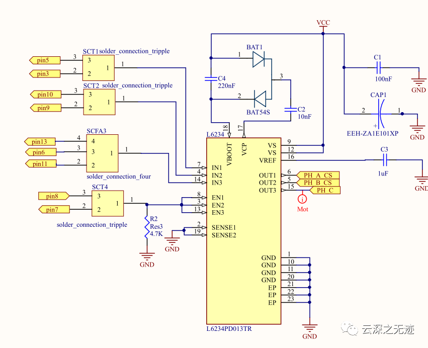
[SimpleFoc-原理圖(STL6234+INA240)]

所以一個(gè)輸出要兩個(gè)接口控制
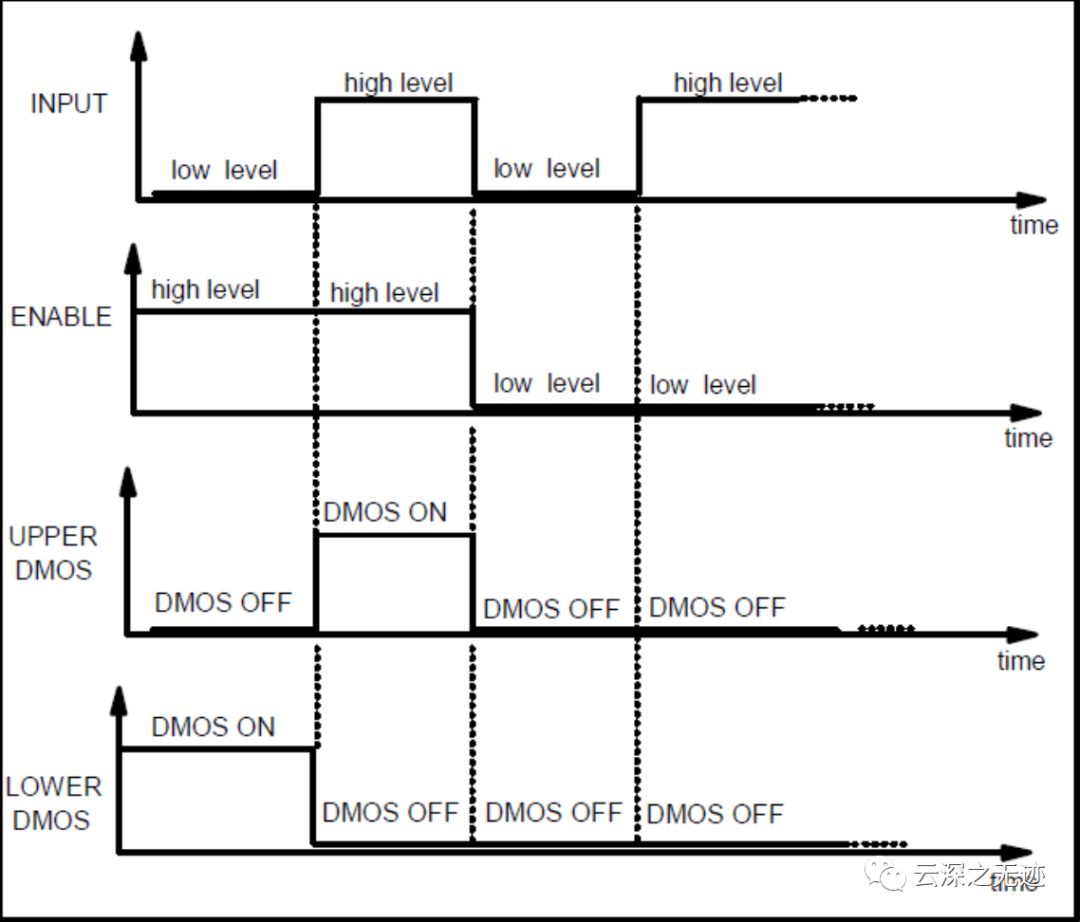
L6234 驅(qū)動(dòng)器有 3 個(gè)輸出:OUT1、OUT2 和 OUT3。每個(gè)輸出由 2 個(gè)引腳控制:輸入 (IN) 和使能 (EN),例如 OUT1 由 IN1 和 EN1 控制。下圖顯示了每個(gè)半橋的控制邏輯:

邏輯電平

輸出電平

另外這個(gè)原理圖看左邊,為了方便可以把使能腳直接都拉低

這樣使用三個(gè)引腳模擬也是可以的
1.L6234 三相電機(jī)驅(qū)動(dòng)器
2.6 x 33k 歐姆電阻器
3.3 x 10k 歐姆電阻器
4.4 x 1 歐姆電阻器(功率為 2 W 或更高)
5.2 x 1N4148 二極管
6.100 uF 電解電容器(16V 或更高)
7.1 uF 電解電容器(16V 或更高)
8.220 nF (0.22 uF) 陶瓷電容器
9.100 nF (0.1 uF) 陶瓷電容器
10.10 nF (0.01 uF) 陶瓷電容器
11.2 x 按鈕
12.12V 電源
#define SPEED_UP A0
#define SPEED_DOWN A1
#define PWM_MAX_DUTY 255
#define PWM_MIN_DUTY 50
#define PWM_START_DUTY 100


byte bldc_step = 0, motor_speed;
unsigned int i;
void setup()
{
    DDRD |= 0x38; // Configure pins 3, 4 and 5 as outputs
    PORTD = 0x00;
    DDRB |= 0x0E; // Configure pins 9, 10 and 11 as outputs
    PORTB = 0x31;
    // Timer1 module setting: set clock source to clkI/O / 1 (no prescaling)
    TCCR1A = 0;
    TCCR1B = 0x01;
    // Timer2 module setting: set clock source to clkI/O / 1 (no prescaling)
    TCCR2A = 0;
    TCCR2B = 0x01;
    // Analog comparator setting
    ACSR = 0x10; // Disable and clear (flag bit) analog comparator interrupt
    pinMode(SPEED_UP, INPUT_PULLUP);
    pinMode(SPEED_DOWN, INPUT_PULLUP);
}
// Analog comparator ISR
ISR(ANALOG_COMP_vect)
{
    // BEMF debounce
    for (i = 0; i < 10; i++)
    {
        if (bldc_step & 1)
        {
            if (!(ACSR & 0x20))
                i -= 1;
        }
        else
        {
            if ((ACSR & 0x20))
                i -= 1;
        }
    }
    bldc_move();
    bldc_step++;
    bldc_step %= 6;
}
void bldc_move()
{ // BLDC motor commutation function switch(bldc_step){ case 0: AH_BL(); BEMF_C_RISING(); break; case 1: AH_CL(); BEMF_B_FALLING(); break; case 2: BH_CL(); BEMF_A_RISING(); break; case 3: BH_AL(); BEMF_C_FALLING(); break; case 4: CH_AL(); BEMF_B_RISING(); break; case 5: CH_BL(); BEMF_A_FALLING(); break; } } void loop() { SET_PWM_DUTY(PWM_START_DUTY); // Setup starting PWM with duty cycle = PWM_START_DUTY i = 5000; // Motor start while(i > 100) {
    delayMicroseconds(i);
    bldc_move();
    bldc_step++;
    bldc_step %= 6;
    i = i - 20;
}
motor_speed = PWM_START_DUTY;
ACSR |= 0x08; // Enable analog comparator interrupt
while (1)
{
    while (!(digitalRead(SPEED_UP)) && motor_speed < PWM_MAX_DUTY)
    {
        motor_speed++;
        SET_PWM_DUTY(motor_speed);
        delay(100);
    }
    while (!(digitalRead(SPEED_DOWN)) && motor_speed > PWM_MIN_DUTY)
    {
        motor_speed--;
        SET_PWM_DUTY(motor_speed);
        delay(100);
    }
}
}


void BEMF_A_RISING()
{
    ADCSRB = (0 << ACME); // Select AIN1 as comparator negative input
    ACSR |= 0x03;         // Set interrupt on rising edge
}
void BEMF_A_FALLING()
{
    ADCSRB = (0 << ACME); // Select AIN1 as comparator negative input
    ACSR &= ~0x01;        // Set interrupt on falling edge
}
void BEMF_B_RISING()
{
    ADCSRA = (0 << ADEN); // Disable the ADC module
    ADCSRB = (1 << ACME);
    ADMUX = 2; // Select analog channel 2 as comparator negative input
    ACSR |= 0x03;
}
void BEMF_B_FALLING()
{
    ADCSRA = (0 << ADEN); // Disable the ADC module
    ADCSRB = (1 << ACME);
    ADMUX = 2; // Select analog channel 2 as comparator negative input
    ACSR &= ~0x01;
}
void BEMF_C_RISING()
{
    ADCSRA = (0 << ADEN); // Disable the ADC module
    ADCSRB = (1 << ACME);
    ADMUX = 3; // Select analog channel 3 as comparator negative input
    ACSR |= 0x03;
}
void BEMF_C_FALLING()
{
    ADCSRA = (0 << ADEN); // Disable the ADC module
    ADCSRB = (1 << ACME);
    ADMUX = 3; // Select analog channel 3 as comparator negative input
    ACSR &= ~0x01;
}


void AH_BL()
{
    PORTB = 0x04;
    PORTD &= ~0x18;
    PORTD |= 0x20;
    TCCR1A = 0;    // Turn pin 11 (OC2A) PWM ON (pin 9 & pin 10 OFF)
    TCCR2A = 0x81; //
}
void AH_CL()
{
    PORTB = 0x02;
    PORTD &= ~0x18;
    PORTD |= 0x20;
    TCCR1A = 0;    // Turn pin 11 (OC2A) PWM ON (pin 9 & pin 10 OFF)
    TCCR2A = 0x81; //
}
void BH_CL()
{
    PORTB = 0x02;
    PORTD &= ~0x28;
    PORTD |= 0x10;
    TCCR2A = 0;    // Turn pin 10 (OC1B) PWM ON (pin 9 & pin 11 OFF)
    TCCR1A = 0x21; //
}
void BH_AL()
{
    PORTB = 0x08;
    PORTD &= ~0x28;
    PORTD |= 0x10;
    TCCR2A = 0;    // Turn pin 10 (OC1B) PWM ON (pin 9 & pin 11 OFF)
    TCCR1A = 0x21; //
}
void CH_AL()
{
    PORTB = 0x08;
    PORTD &= ~0x30;
    PORTD |= 0x08;
    TCCR2A = 0;    // Turn pin 9 (OC1A) PWM ON (pin 10 & pin 11 OFF)
    TCCR1A = 0x81; //
}
void CH_BL()
{
    PORTB = 0x04;
    PORTD &= ~0x30;
    PORTD |= 0x08;
    TCCR2A = 0;    // Turn pin 9 (OC1A) PWM ON (pin 10 & pin 11 OFF)
    TCCR1A = 0x81; //
}


void SET_PWM_DUTY(byte duty)
{
    if (duty < PWM_MIN_DUTY)
        duty = PWM_MIN_DUTY;
    if (duty > PWM_MAX_DUTY)
        duty = PWM_MAX_DUTY;
    OCR1A = duty; // Set pin 9  PWM duty cycle
    OCR1B = duty; // Set pin 10 PWM duty cycle
    OCR2A = duty; // Set pin 11 PWM duty cycle
}
代碼我就先不解釋了,看懂需要看ATmega的書手冊(cè)
這個(gè)是ATmega的中文數(shù)據(jù)手冊(cè)了:
鏈接:https://pan.baidu.com/s/13Bg6A6KGsjhuScStLKJt9Q 提取碼:3lna
-
電機(jī)驅(qū)動(dòng)
+關(guān)注
關(guān)注
60文章
1215瀏覽量
86724 -
源碼
+關(guān)注
關(guān)注
8文章
639瀏覽量
29185 -
代碼
+關(guān)注
關(guān)注
30文章
4779瀏覽量
68525
發(fā)布評(píng)論請(qǐng)先 登錄
相關(guān)推薦
無刷直流電機(jī)驅(qū)動(dòng)電路
L6234無刷直流電機(jī)控制-簡(jiǎn)易版
無刷直流電機(jī)的原理與驅(qū)動(dòng)
基于Matlab/Simulink的無刷直流電機(jī)控制仿真研究
無刷直流電機(jī)運(yùn)行原理與基本控制

永磁無刷直流電機(jī)簡(jiǎn)介

無刷直流電機(jī)原理

無刷直流電機(jī)與有刷直流電機(jī)的區(qū)別


 L6234無刷直流電機(jī)控制


評(píng)論