ubuntu20.04+vscode下對杰發科技的AC7802x Cortex-M0+進行編程、編譯、下載等。
開發板
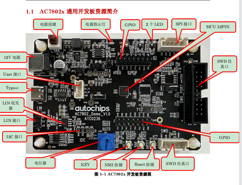
開發板為杰發科技的AC780x,板載的主控芯片為AC78022,32PIN。內核為Cortex-M0+。

流程圖

控制部分的原理圖
1、本次實驗選用LED1來實現燈的開與關。原理圖如下:


從原理圖上看,LED1控制IO接到PA2,高電平制三極管導通,LED1亮,反之則關斷。
串口選擇
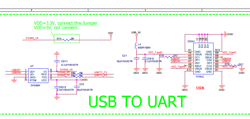
從開發板原理圖上,uart1接到了ch340,并配備了typc接口,本次實驗選用uart1為實驗串口。

實驗步聚
-
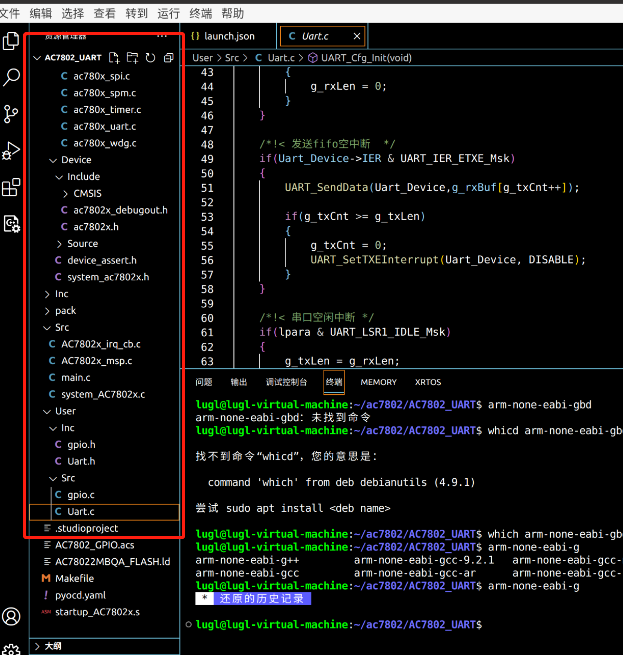
拷貝一份模版到AC7802_UART。并用vscode打開。

-
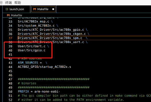
在User/Src下新建Uart.c,gpio.c,在Inc目錄下新建Uart.h、gpio.h,并把Uart.c、gpio.c加入到makefile的source中

-
編寫gpio.h 以及 gpio.c的Led初始化代碼:
#ifndef _GPIO_H__
#define _GPIO_H__

#include "ac780x_gpio.h"

#define LED1_PORT           (GPIOA)
#define LED1_PIN            (GPIO_PIN2)


/*LED1動作定義.*/
#define LED1_ON             do{GPIO_SetPinLevel(LED1_PORT, LED1_PIN, GPIO_LEVEL_HIGH);}while(0)
#define LED1_OFF            do{GPIO_SetPinLevel(LED1_PORT, LED1_PIN, GPIO_LEVEL_LOW);}while(0)
#define LED1_TOGGLE         do{if(GPIO_GetPinLevel(LED1_PORT, LED1_PIN)){LED1_OFF;}else{LED1_ON;}}while(0)


void GPIO_LedInit(void);


#endif
gpio.c
#include "gpio.h"
#include "stdbool.h"

void GPIO_LedInit(void)
{
    /*初始化引腳功能,如果引腳上電后默認為GPIO,可省略掉初始化步驟.
      有部分引腳上電默認為非GPIO,則必須選擇其功能為GPIO才能作為GPIO使用.*/
    GPIO_SetFunc(LED1_PORT, LED1_PIN, GPIO_FUN0);/*! 功能復用選擇.*/


    /*! 設置LED引腳為GPIO輸出.*/
    GPIO_SetDir(LED1_PORT, LED1_PIN, GPIO_OUT);


    LED1_ON;

}
- 編寫uart.h、usrt.c內容如下:
#ifndef __UART_H__
#define __UART_H__
#include "ac780x_uart.h"

void UART_Cfg_Init(void);

#endif
uart.c
/* ===========================================  Includes  =========================================== */
#include < stdbool.h >
#include "ac780x_gpio.h"
#include "ac780x_uart_reg.h"
#include "Uart.h"


/* ============================================  Define  ============================================ */
#define RX_BUF_LEN   100U

/* ===========================================  Typedef  ============================================ */


/* ==========================================  Variables  =========================================== */
uint8_t g_rxLen  = 0;                 /*!< 串口接收長度變量 */
uint8_t g_txLen  = 0;                 /*!< 串口發送長度變量 */
uint8_t g_txCnt  = 0;
uint8_t g_rxBuf[RX_BUF_LEN] = {0};    /*!< 串口接收數組 */
uint8_t g_rec_state = 0;
/* ====================================  Functions declaration  ===================================== */


/* ======================================  Functions define  ======================================== */

/*!
 * @brief   串口回調函數
 *
 * @param   void *device:UART_Type pointer
            uint32_t wpara:UART lsr0 register
            uint32_t lpara:UART lsr1 register
 * @return  none
 */
void UART_Callback(void *device, uint32_t wpara, uint32_t lpara)
{
    UART_Type *Uart_Device = (UART_Type *)device;

    /*! 串口接收中斷 */
    if(wpara & UART_LSR0_DR_Msk)
    {
        g_rxBuf[g_rxLen++] = UART_ReceiveData(Uart_Device);

        if(g_rxLen > RX_BUF_LEN)
        {
            g_rxLen = 0;
        }
    }

    /*!< 發送fifo空中斷  */
    if(Uart_Device- >IER & UART_IER_ETXE_Msk)
    {
        UART_SendData(Uart_Device,g_rxBuf[g_txCnt++]);

        if(g_txCnt >= g_txLen)
        {
            g_txCnt = 0;
            UART_SetTXEInterrupt(Uart_Device, DISABLE);
        }
    }

    /*!< 串口空閑中斷 */
    if(lpara & UART_LSR1_IDLE_Msk)
    {
        g_rec_state = 1;

        //UART_SetTXEInterrupt(Uart_Device, ENABLE);
    }
}

/*!
 * @brief   uart configuration init
 *
 * @param   none
 * @return  none
 */
void UART_Cfg_Init(void)
{
    UART_ConfigType uart_config;

    GPIO_SetFunc(GPIOA, GPIO_PIN4, GPIO_FUN3);    /*! uart tx */
    GPIO_SetFunc(GPIOA, GPIO_PIN5, GPIO_FUN3);    /*! uart rx */

    uart_config.baudrate   = 115200;              /*! 波特率115200 */
    uart_config.dataBits   = UART_WORD_LEN_8BIT;  /*! 數據8bit */
    uart_config.stopBits   = UART_STOP_1BIT;      /*! 停止位1bit */
    uart_config.fifoByteEn = DISABLE;
    uart_config.sampleCnt  = UART_SMP_CNT0;       /*! 16倍采樣 */
    uart_config.callBack   = UART_Callback;       /*! 回調函數設置 */

    UART_Init(UART1,&uart_config);                /*! 串口初始化 */

    UART_SetRXNEInterrupt(UART1, ENABLE);         /*! 串口接收中斷使能 */

    UART_SetIdleFuncEn(UART1, ENABLE);
    UART_SetIdleInterrupt(UART1, ENABLE);         /*! 使能串口空閑中斷 */

    NVIC_SetPriority(UART1_IRQn, 3);              /*! 串口中斷優先級 */
    NVIC_ClearPendingIRQ(UART1_IRQn);
    NVIC_EnableIRQ(UART1_IRQn);
}


 ubuntu下編程——杰發科技AC7802x串口控制LED燈