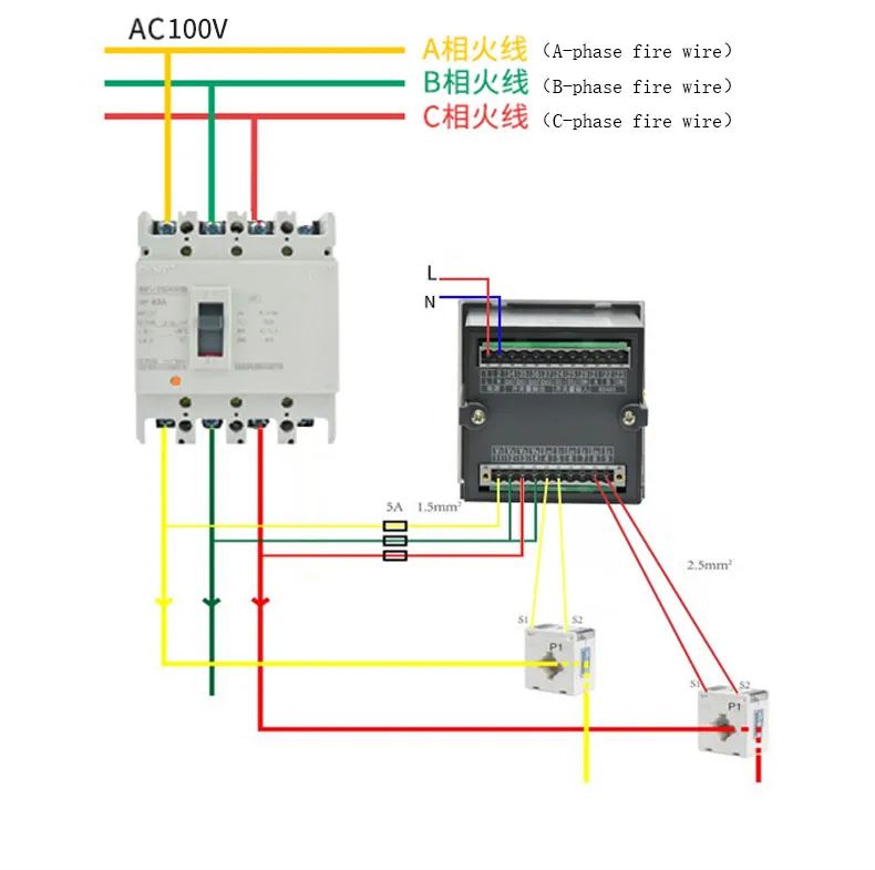
三相三線圖
Three-phase three-wire diagram
1、端子數目1和2為輔助電源: 如上圖所示,連接相電壓220v 輸入。其中,輔助電源的火線裝有5A 熔斷器,中性線直接連接到零線銅條上。
Terminal numbers 1 and 2 are auxiliary power supply: as shown in the figure above, connect the phase voltage 220V input. Among them, the fire wire of the auxiliary power supply is installed 5A fuse, the neutral wire is directly connected to the zero line copper bar.
2、電壓接線:在三相三線的情況下,電壓信號端子以V型接線方式連接,11連接到A相電壓,12連接到B相電壓,13連接到C電壓,14連接到B相電壓,電壓線為1.5平方BVR多芯硬線,帶電線連接到儀表。他們之間需要安裝一個5A保險絲。Voltage wiring:In the case of three-phase three-wire, the voltage signal terminals are connected in V-shaped wiring mode, 11 is connected to A-phase voltage, 12 is connected to B-phase voltage, 13 is connected to C voltage and 14 is connected to B-phase voltage ; the voltage wire is a 1.5 square BVR multi-core hard wire, and the live wire is connected to the meter. A 5A fuse needs to be installed between them.
3、電流接線:在三相三線的情況下,電流信號端子連接成V形,變壓器的一次電流從P1側流向 P2側; 互感器的輸出 S1連接到第4端子,S2連接到第5端子,C互感器S1連接到第8端子,S2連接到9個端子,其中帶 * 的端子連接到變壓器的 S1端子,電流采用2.5平方BVR多芯硬線。
Current wiring:In the case of three-phase three-wire, the current signal terminals are connected in a V-shape, and the primary current of the transformer flows from the P1 side to the P2 side ; the output S1 of the A mutual inductor is connected to the 4th terminal, S2 is connected to the 5th terminal, the C mutual inductor S1 is connected to the 8th terminal, and S2 Connect to 9 terminals, of which the terminal with * corresponds to the S1 terminal of the transformer ; the current wire uses a 2.5 square BVR multi-core hard wire.
4、通信終端:RS485 (A+, B-) A 連接到端口21,B連接到端口22,使用RVSP2*1.0平方芯雙絞線屏蔽柔性導線。Communication terminals: RS485 (A+, B-) A is connected to port 21, B is connected to port 22, use RVSP2*1.0 square Core twisted pair shielded flexible wire.
5、一定要按照說明接線,錯誤的接線會導致測量不準確。儀表的側面標簽上有接線圖。
Be sure to wire according to the instructions, wrong connection will lead to inaccurate measurement. There are wiring diagrams on the side labels of the meter.
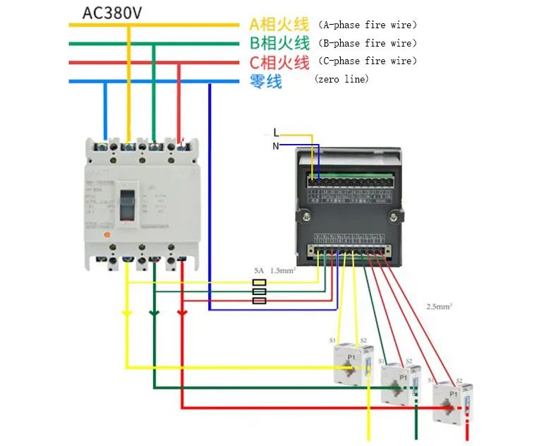
三相四線圖
Three-phase four-wire diagram
1、端子數目1和2為輔助電源: 如上圖所示,連接相電壓220V輸入。輔助電源裝有5A保險絲,連接到零排。其中,中性線的火線是直接。
Terminal numbers 1 and 2 are auxiliary power supply: as shown in the figureabove, connect the phase voltage 220V input. auxiliary power supply is installed 5A fuse, connected to the zero row.
2、電壓接線:在三相四線制情況下,電壓信號端子以Y型接線方式連接,分別對應于11相電壓、12相電壓、13至C電壓和14至N線; 電壓線采用1.5平方BVR多芯硬線,通電線與儀表之間應安裝5A熔斷器。
Voltage wiring:In the case of three-phase four-wire, the voltage signal terminals are connected in a Y-shaped wiring mode, respectively corresponding to 11 connected to A-phase voltage, 12 to B-phase voltage, 13 to C voltage and 14 to N line; the voltage line uses a 1.5 square BVR multi-core hard wire , a 5A fuse should be installed between the live wire and the meter.
3、電流接線: 在三相三線的情況下,電流信號端子連接成V形,變壓器的一次電流從P1側流向P2側; 互感器的輸出S1連接到第4端子,S2連接到第5端子,C互感器 s1連接到第8端子,S2連接到9個端子,其中帶 * 的端子連接到變壓器的S1端子,電流采用2.5平方BVR多芯硬線。
Current wiring:In the case of three-phase three-wire, the current signal terminals areconnected in a V-shape, and the primary current of the transformer flows from the P1 side to the P2 side; the output S1 of the A mutual inductor is connected to the 4th terminal, S2 is connected to the 5th terminal, the C mutual inductor S1 is connected to the 8th terminal, and S2 Connect to 9 terminals, of which the terminal with * corresponds to the S1 terminal of the transformer ; the current wire uses a 2.5 square BVR multi-core hard wire.
4、通信終端:RS485 (A+, B-) A 連接到端口21,B連接到端口22,使用 RVSP2*1.0平方多核雙絞線屏蔽軟線。
Communication terminals: RS485 (A+, B-) A is connected to port 21, B is connected to port 22, use RVSP2*1.0 square multi-core twisted pair shielded flexible wire.
5、一定要按照說明接線,錯誤的接線會導致測量不準確。儀表的側面標簽上有接線圖。
Be sure to wire according to the instructions, wrong connection will lead to inaccurate measurement. There are wiring diagrams on the side labels of the meter.
-
多功能
+關注
關注
0文章
85瀏覽量
19123 -
接線
+關注
關注
29文章
726瀏覽量
33231
發布評論請先 登錄
相關推薦
分布式光伏380v并網交流電能計量多功能儀表 IEC標準
什么是三相多功能電力儀表?有什么作用?
三相多功能用電檢查儀的接線說明——每日了解電力知識

多功能數顯表的功能特點有哪些?
安科瑞PZ42-E4系列三相智能多功能電測儀表
三相液晶多功能電力儀表 BE151系列說明書
三相數顯多功能電力儀表BE150系列說明書
安科瑞多功能電力儀表在莫桑比克某農場的應用
ACRELADL系列多功能電能表在迪拜大廈EMS中的應用


 多功能儀表接線說明Acrel Multi-function Meter Wiring Instruction


評論