在數字化技術在各個領域得到廣泛運用的今天,數字濾波器是數字系統中信號處理關鍵的一環。數字濾波在圖像處理、語音識別和模式識別等數字信號處理中占有重要地位。數字濾波器和模擬濾波器相比具有更高的精度、信噪比,以及不可比擬的可靠性。由于在性能、成本、靈活性和功耗等方面的優勢,基于fpga的信號處理器已廣泛應用于各種信號處理領域。
本文主要介紹了基于現場可編程門陣列(fpga)技術fir數字濾波器的設計,設計一個濾波器,其采樣率 fs=1MHz,通帶截止頻率 fpass=50KHz,歸一化表示fpass=0.1,阻帶起始頻率 fstop=200 KHz,歸一化表示為fstop=0.4,阻帶衰減 80dB。
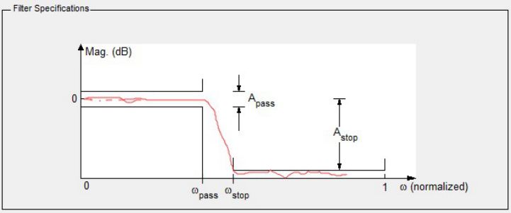
設計實現
1. 打開 MATLAB 軟件,在命令行窗口輸入 fdatool 并回車,打開濾波器設計與分析工具窗口
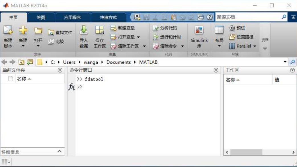
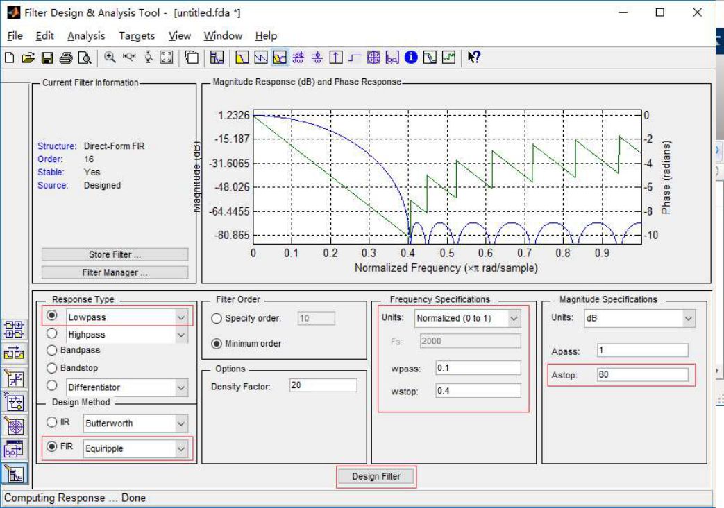
2. 在 fda 工具中配置你需要的濾波器參數
圖片中頻率參數(frequency specifications)采用的歸一化表示方法,如果使用實際頻率表示,在 Units 框內選擇“KHz”;
在 Fs 內填寫 1000,即數字采樣頻率為1000KHz (1MHz);在 Fpass 內填寫 50,即通帶截止頻率為 50KHz;在 Fstop內填寫 200,即阻帶起始頻率為 200KHz,Astop 填 80,即為阻帶衰減 80dB。
點擊 Design Filter 后可以查看頻率及相位的響應曲線
3.在“Filter Designer & Analysis Tool”界面中,打開 File—>Export…出現下圖
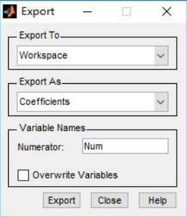
4.點擊“Export” 將系數導出到 MATLAB 工作區間
將 coefficients 系數保存到 txt 文件中,在 MATLAB 命令窗口輸入:
>> fid=fopen('F:Fpga_ProjectFIR_Filtercoef.txt','w');
% txt 文件路徑根據實際情況修改
>> fprintf(fid,'%d,',Num); % 打印到 txt 文件中的相鄰系數由逗號隔開
>> fclose(fid);

這樣我們就得到了一組濾波器系數,存在上圖路徑下的 coef.txt 文件中。
打開 quartus prime 17.0 軟件,新建工程:
5.工程名字:FIR_Fliter
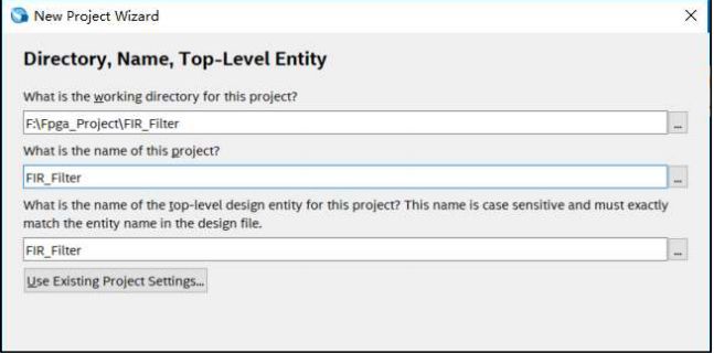
6.選擇對應的 FPGA 型號,10M08SCM153C8G

7.根據自己的情況選擇 EDA 工具,這里我們選擇 synplify pro 和 Modelsim-Altera
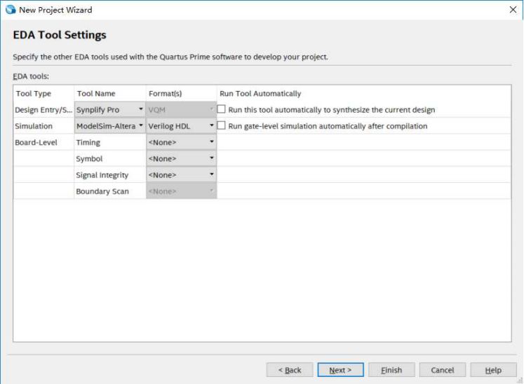
完成新建工程,進入開發界面;
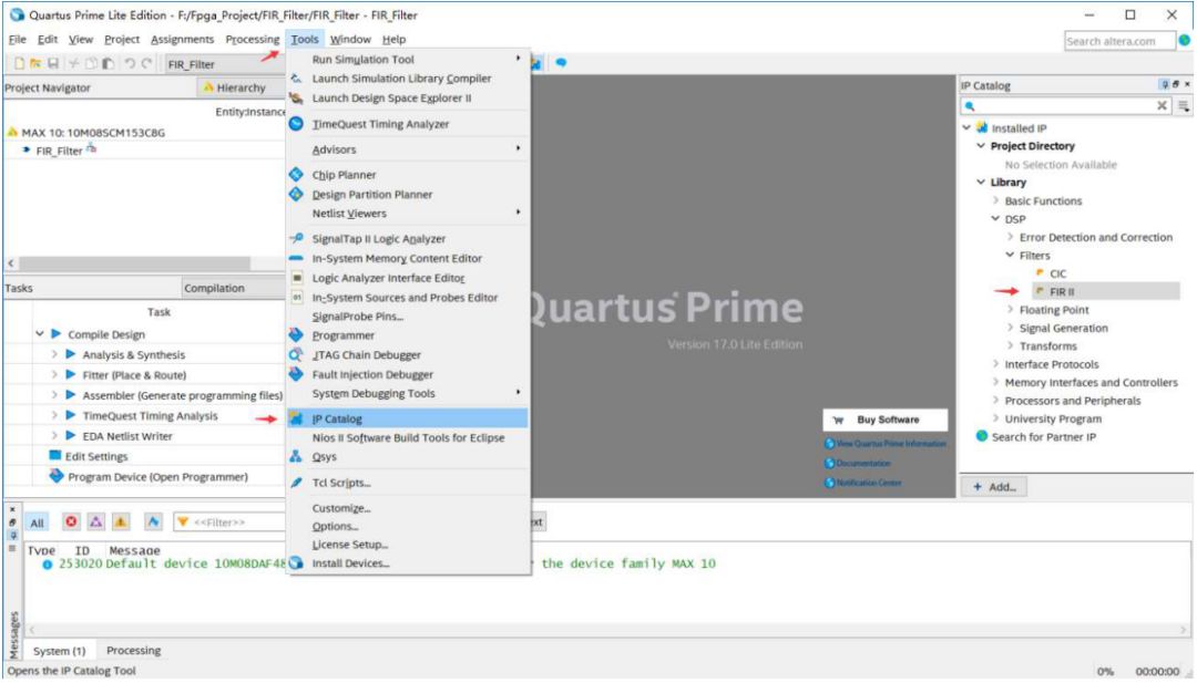
8.在開發界面選擇 tools—>IP Catalog,并在 IP Library 中找到 FIR II 的選項,雙加 FIR II 打開 QSYS 工具
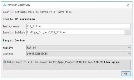
9.填寫 IP 實例的名字,點擊 OK
10.在 Filter Specification 選項中配置參數如下圖

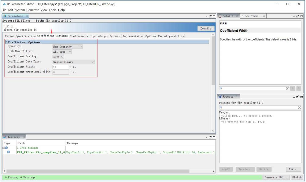
11.在 Coefficient Settings 選項中配置參數如下圖
Coefficient width 可以自行配置,一般值越高濾波效果也好,同時實現濾波器消耗的資源也越多
12.在 Coefficients 選項中需要將 Matlab 中導出的濾波系數導入
點擊 Import from file 按鈕,選擇之前從 Matlab 導出的 coef.txt 文件,點擊 import 導入;
軟件會將導入的系數按照上圖中設定的系數位寬調整到合適的值,并分別繪制響應曲線,原始數據 VS 修正數據


13.在 Input/Output Opetion 選項中配置參數
如下圖,其中 Input width 根據采樣數據的實際位寬填寫,這里為 11 位有符號數

14.以上各項參數配置完成后,點擊 Generate HDL..,彈出生成頁面,點擊 Generate,等待完成

通過以上操作完成了 IP 核的生成,點擊 Finish 結束。

15.將 IP 核中的 qip 和 sip 文件添加到工程文件列表中
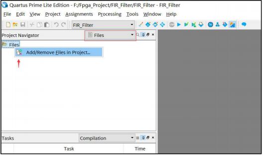

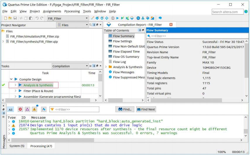
16.對工程進行綜合,通過
17.將我們準備好的測試文件 FIR_filter_tb.v 和 DDS.v 拷貝至工程目錄文件夾下
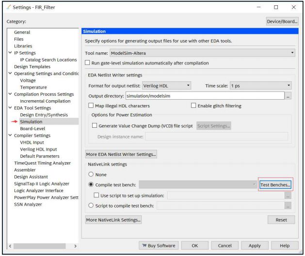
在 Quartus prime 17.0 軟件中選擇
Assignment —>settings.. —>EDA tool settings —>Simulation —>Test Benches 添加仿真文件
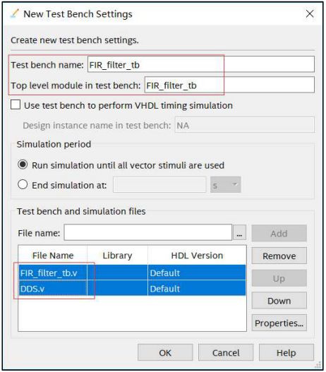
18.點擊 Tools —>RUN Simulation Tool —>RTL Simulation
Quartus prime 17.0 支持一鍵式仿真,直接啟動仿真軟件 Modelsim-Altera,并顯示仿真波形數據(模擬形式顯示)
data1 信號為 24KHz 正弦波,量化位寬為 10bit
data2 信號為 240KHz 正弦波,量化位寬為 10bit
data_in 信號為 data1 和 data2 的疊加信號,量化位寬為 11bit
data_out 信號為 data_in 信號經過 FIR 數字濾波后的輸出,量化位寬為 28bit
附件一:FIR_filter_tb.v
// --------------------------------------------------------------------
// >>>>>>>>>>>>>>>>>>>>>>>>> COPYRIGHT NOTICE <<<<<<<<<<<<<<<<<<<<<<<<
// --------------------------------------------------------------------
// Module: FIR_filter_tb
//
// Author: Step
//
// Description: FIR_filter_tb
//
// Web: www.stepfpga.com
//
// --------------------------------------------------------------------
// Code Revision History :
// --------------------------------------------------------------------
// Version: |Mod. Date: |Changes Made:
// V1.1 |2016/10/30 |Initial ver
// --------------------------------------------------------------------
`timescale 1ps/1ps
module FIR_filter_tb;
parameter PERIOD = 20;
reg clk, rst_n;
wire signed [26:0] data_out;
initial begin
clk = 0;
rst_n = 0;
#100;
rst_n = 1;
#6000;
$stop;
end
always #10 clk = ~clk;
wire signed[9:0] data1;
DDS dds_24k
(
.clk_in(clk), //clock in
.rst_n_in(rst_n), //reset, active low
.dds_en_in(1), //dds work enable
.f_increment(24'h60000), //frequency increment
.p_increment(0), //phase increment
.dac_data_out(data1) //data out
);
wire signed[9:0] data2;
DDS dds_240k
(
.clk_in(clk), //clock in
.rst_n_in(rst_n), //reset, active low
.dds_en_in(1), //dds work enable
.f_increment(24'h3c0000), //frequency increment
.p_increment(0), //phase increment
.dac_data_out(data2) //data out
);
wire signed[10:0] data_in = data1 + data2;
FIR_Filter u0 (
.ast_sink_data (data_in), // avalon_streaming_sink.data
.ast_sink_valid (1), // .valid
.ast_sink_error (0), // .error
.ast_source_data (data_out), // avalon_streaming_source.data
.ast_source_valid (), // .valid
.ast_source_error (), // .error
.clk (clk), // clk.clk
.reset_n (rst_n) // rst.reset_n
);
endmodule
附件二:DDS.v
// --------------------------------------------------------------------
// >>>>>>>>>>>>>>>>>>>>>>>>> COPYRIGHT NOTICE <<<<<<<<<<<<<<<<<<<<<<<<
// --------------------------------------------------------------------
// Module: DDS
//
// Author: Step
//
// Description: DDS
//
// Web: www.stepfpga.com
//
// --------------------------------------------------------------------
// Code Revision History :
// --------------------------------------------------------------------
// Version: |Mod. Date: |Changes Made:
// V1.1 |2016/10/30 |Initial ver
// --------------------------------------------------------------------
module DDS
(
input clk_in, //clock in
input rst_n_in, //reset, active low
input dds_en_in, //dds work enable
input [23:0] f_increment, //frequency increment
input [23:0] p_increment, //phase increment
output dac_clk_out, //clock out
output [9:0] dac_data_out //data out
);
reg [23:0] phase_accumulator;
wire [23:0] phase;
//wire [9:0] dac_data_out;
assign dac_clk_out = clk_in;
//next_phase = phase_accumulator + f_increment;
always @(posedge clk_in or negedge rst_n_in)
begin
if(!rst_n_in) phase_accumulator <= 23'b0;
else if(dds_en_in) phase_accumulator <= phase_accumulator + f_increment;
end
assign phase = phase_accumulator + p_increment; // phase is the high 8 bits
lookup_table lookup_table_uut
(
.phase(phase[23:16]),
.dac_data_out(dac_data_out)
);
endmodule
/**************************************************
module: lookup_table
**************************************************/
module lookup_table
(
input [7:0] phase,
output reg [9:0] dac_data_out
);
wire [5:0] address = phase[5:0];
wire [1:0] sel = phase[7:6];
wire [9:0] sine;
always@(sel or sine)
case (sel)
2'b00 : dac_data_out = {1'b0, sine[9:1]};
2'b01 : dac_data_out = {1'b0, sine[9:1]};
2'b10 : dac_data_out = {1'b1, 9'h1ff-sine[9:1]};
2'b11 : dac_data_out = {1'b1, 9'h1ff-sine[9:1]};
endcase
sine_table sine_table_uut
(
.sel(sel),
.address(address),
.sine(sine)
);
endmodule
/**************************************************
module: sine_table
**************************************************/
module sine_table
(
input [1:0] sel,
input [5:0] address,
output reg [9:0] sine
);
reg [5:0] table_addr;
always @(sel or address)
case (sel)
2'b00: table_addr = address;
2'b01: table_addr = 6'h3f - address;
2'b10: table_addr = address;
2'b11: table_addr = 6'h3f - address;
endcase
always @(table_addr)
case(table_addr)
6'h0: sine=10'h000;
6'h1: sine=10'h019;
6'h2: sine=10'h032;
6'h3: sine=10'h04B;
6'h4: sine=10'h064;
6'h5: sine=10'h07D;
6'h6: sine=10'h096;
6'h7: sine=10'h0AF;
6'h8: sine=10'h0C4;
6'h9: sine=10'h0E0;
6'ha: sine=10'h0F9;
6'hb: sine=10'h111;
6'hc: sine=10'h128;
6'hd: sine=10'h141;
6'he: sine=10'h159;
6'hf: sine=10'h170;
6'h10: sine=10'h187;
6'h11: sine=10'h19F;
6'h12: sine=10'h1B5;
6'h13: sine=10'h1CC;
6'h14: sine=10'h1E2;
6'h15: sine=10'h1F8;
6'h16: sine=10'h20E;
6'h17: sine=10'h223;
6'h18: sine=10'h238;
6'h19: sine=10'h24D;
6'h1a: sine=10'h261;
6'h1b: sine=10'h275;
6'h1c: sine=10'h289;
6'h1d: sine=10'h29C;
6'h1e: sine=10'h2AF;
6'h1f: sine=10'h2C1;
6'h20: sine=10'h2D3;
6'h21: sine=10'h2E5;
6'h22: sine=10'h2F6;
6'h23: sine=10'h307;
6'h24: sine=10'h317;
6'h25: sine=10'h326;
6'h26: sine=10'h336;
6'h27: sine=10'h344;
6'h28: sine=10'h353;
6'h29: sine=10'h360;
6'h2a: sine=10'h36D;
6'h2b: sine=10'h37A;
6'h2c: sine=10'h386;
6'h2d: sine=10'h392;
6'h2e: sine=10'h39C;
6'h2f: sine=10'h3A7;
6'h30: sine=10'h3B1;
6'h31: sine=10'h3BA;
6'h32: sine=10'h3C3;
6'h33: sine=10'h3CB;
6'h34: sine=10'h3D3;
6'h35: sine=10'h3DA;
6'h36: sine=10'h3E0;
6'h37: sine=10'h3E6;
6'h38: sine=10'h3EB;
6'h39: sine=10'h3F0;
6'h3a: sine=10'h3F3;
6'h3b: sine=10'h3F7;
6'h3c: sine=10'h3FA;
6'h3d: sine=10'h3FC;
6'h3e: sine=10'h3FE;
6'h3f: sine=10'h3FF;
endcase
endmodule
-
FPGA
+關注
關注
1630文章
21759瀏覽量
604301 -
濾波器
+關注
關注
161文章
7845瀏覽量
178393 -
信號處理器
+關注
關注
1文章
254瀏覽量
25303
原文標題:【FPGA信號處理一】5分鐘學會FIR 濾波器設計
文章出處:【微信號:gh_873435264fd4,微信公眾號:FPGA技術聯盟】歡迎添加關注!文章轉載請注明出處。
發布評論請先 登錄
相關推薦
使用FPGA構建的數字濾波器設計方案

基于IP核的FIR低通濾波器該怎么設計?
如何優化FIR數字濾波器?
用CPLD實現FIR數字濾波器的設計
基于LabVIEW的FIR數字濾波器設計

基于MATLAB及FPGA的FIR低通濾波器的設計

基于FPGA的FIR數字濾波器的優化設計

如何使用FPGA實現IIR數字濾波器的設計


 基于現場可編程門陣列(fpga)技術fir數字濾波器的設計


評論