I2C總線的驗證及實現--Proven Implementations of the I2C Bus
Abstract: This application note briefly reviews the history of the I2C bus. It then presents I2C configurations proven to ensure easy communication between the master and slaves on the bus. Examples include schematics and code. Appendix 1 contains helpful definitions of terms used in this article.
Introduction
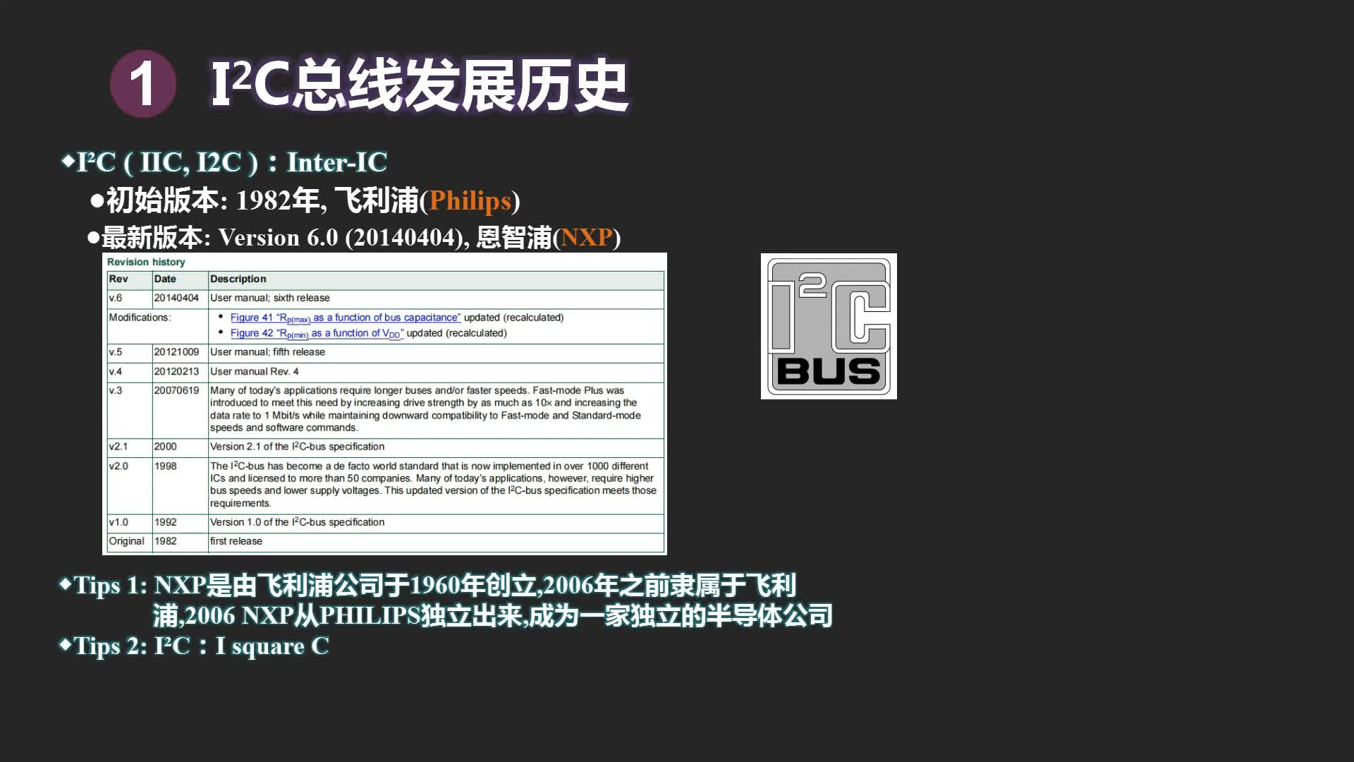
The Inter IC (I2C) bus was developed by Philips Semiconductor in the early 1980s to simplify electronic products by reducing the number of parallel data lines. Version 1.0 of the I2C-bus specification, released by Philips? in 1992, defined a simple,
The I2C bus configurations presented in this article have been proven to ensure easy communication with slave devices on the bus. Each implementation includes examples in the form of schematics and code. The reader should be familiar with the following documents:
- The I2C-Bus Specification, Version 2.1, January 2000.
Philips Semiconductor document #9398 393 40011. - The I2C-bus and how to use it, April 1995.
Philips Semiconductor document #98-8080-575-01. - System Management Bus (SMBus?) Specification, Version 2.0, August 2000.
Background and Discussion
The I2C bus can operate in Standard mode, Fast mode, or High-Speed (Hs) mode, with maximum data rates of 100kbps (Standard mode), 400kbps (Fast mode), 1.7 Mbps (Hs mode with Cb = 400pF), and 3.4Mbps (Hs mode with Cb = 100pF).
The original Standard mode incorporated 7-bit addressing, which allowed 112 slave addresses. As I2C-bus systems demanded more slave devices, 10-bit addressing was introduced to allocate more slave addresses.
Fast mode added useful features to the slave devices. The maximum data rate was quadrupled to 400kbps. Fast-mode I2C also dropped the support of similar buses often linked with the I2C bus, i.e., buses that were no longer compatible with the higher data rate. To suppress noise spikes, Fast-mode devices were given Schmitt-triggered inputs. In addition, the SCL and SDA lines of an I2C-bus slave device were required to exhibit high impedance when power was removed.
Hs mode was created mainly to increase the data rate—up to 36 times faster than Standard mode. For I2C buses operating in Hs mode, the most significant change affects low-to-high transitions on the SCL line. Because the pullup resistors used in Standard and Fast mode cannot produce rise times fast enough to meet the Hs-mode specification, most Hs-mode systems must include active pullups on the SCL line. Other changes include an Hs-mode compatibility request, issued by the Hs-mode master in Standard or Fast mode using an 8-bit master code. If Not-Acknowledge (a bit name within the I2C frame) remains high immediately following the master code, then all communications remain in Hs mode until a stop occurs. The waveforms of Figure 1 illustrate the use of the master code for entering Hs mode.
Figure 1. These waveforms represent a transfer from Standard- or Fast-mode I2C to Hs mode.
Proven Implementations for I2C On-Chip Peripherals
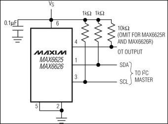
The PIC18F442 microcontroller (μC) includes an I2C peripheral that supports Standard- and Fast-mode I2C. Figure 2 shows an application circuit using that peripheral to collect samples from a 16-bit serial-output ADC (MAX1169). When data is received by the PIC?, it is immediately transmitted at 115kBaud by a firmware UART. The RS-232 transceiver (MAX3232E) then allows the data to be captured by a personal computer's standard serial port. All assembly source files needed to implement Fast-mode I2C on the PIC's on-chip peripheral are contained in the file I2C_on_chip_asm.zip. A tool called MPLAB IDE Version 6.10.00 was used to develop assembly code for the Figure 2 circuit.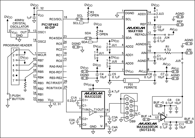
Figure 2. The I2C peripheral internal to this PIC18F442 μC connects to a 16-bit ADC (MAX1169).
Proven Implementations for Bit-Banging I2C
The MAXQ2000 is a low-power 16-bit RISC μC capable of bit-banging Standard-mode, Fast-mode, and even 1.7MHz Hs-mode I2C signals. Figure 3 shows a general-purpose schematic of the MAXQ2000 operating as an I2C master in all three modes. An active pullup is included in the MAXQ2000 to support the 1.7MHz Hs mode. The file I2C_bit_bang_asm.zip contains all assembly source files needed to bit-bang Standard- and Fast-mode I2C systems using the μC's GPIO lines.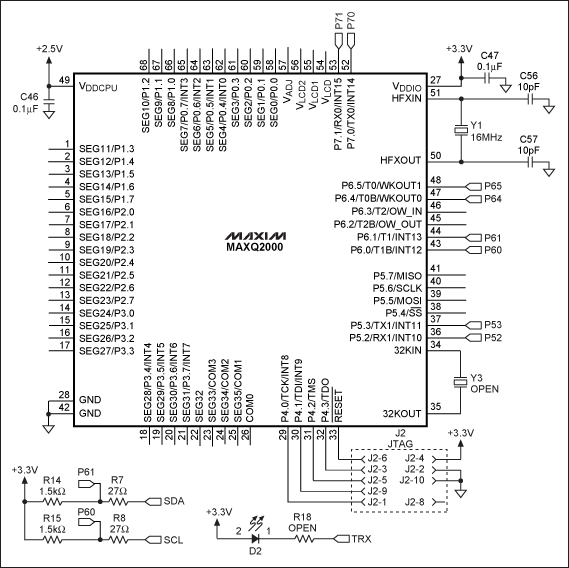
Figure 3. This schematic (based on the MAXQ2000 low-power LCD μC) depicts an I2C master capable of operating in Standard, Fast, or Hs mode.
The default clock speed for the MAXQ2000's I2C firmware is 100kHz, but the μC's 16MHz system clock allows a bit-banged I2C interface to run as fast as 400kHz. The following code example shows how to capture interrupt events and handle them in a simple interrupt-service routine. The development tool used is MAX-IDE Version 1.0 (build date: Nov 18 2004), which can be downloaded for free from the Maxim website.
The file I2C_bit_bang_c.zip contains all the C-source files required to bit-bang a Standard- or Fast-mode I2C link using the MAXQ2000's GPIO lines. This example in Figure 3 is based on a maxqi2c library consisting of two files, maxqi2c.h and
The file HSI2C_bit_bang_asm_c.zip contains all the assembly and C source files required to bit-bang a 1.7MHz Hs-mode I2C link using the MAXQ2000 GPIO lines. By mixing assembly and C code, the source code in this example takes full advantage of the strength of each code type. Assembly optimizes speed, and C accomplishes many things in just a few lines of code. The timing-critical Hs-mode I2C receive function (hsi2cRecv) is defined in the assembly source file hsi2c.asm.
The main C source file initializes the MAXQ2000's UART at 115.2kBaud. For the source code to produce a 1.7MHz Hs-mode I2C link, Y1 in Figure 3 must be a 20MHz crystal. The main C source file calls the hsi2cRecv function when needed, and a printf function transfers data from the on-chip UART, which is set for the 8-N-1 data format. The Rowley CrossWorks IDE Version 1.0 (Build 2 licensed copy) was the development tool used in this example. To obtain the CrossWorks IDE, contact Rowley Associates Limited or visit their website.
Proven Implementations for I2C IP Core Peripherals
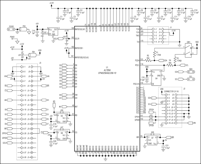
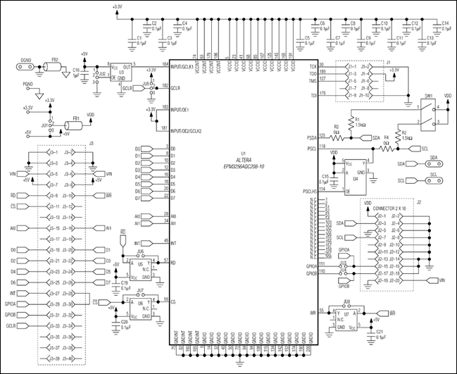
An I2C IP core called DI2CM (by Digital Core Design) is used in many CPLD and FPGA devices. The DI2CM IP core converts a parallel interface to an I2C interface, and implements a true Hs-mode master capable of clock speeds as high as 3.4MHz. In the application circuit of Figure 4, the Altera? EPM3256AQC208-10 CPLD includes a DI2CM IP core. This circuit requires a 40MHz crystal oscillator (U3) to achieve compatibility with both 1.7MHz and 3.4MHz Hs-mode I2C. A 3-state logic buffer with output enable allows the DI2CM IP core to produce an active pullup on the SCL line, as is required by Hs-mode I2C. Logic inverters are provided at U5, U6, and U7 to support both an active-high and an active-low memory-mapped parallel interface.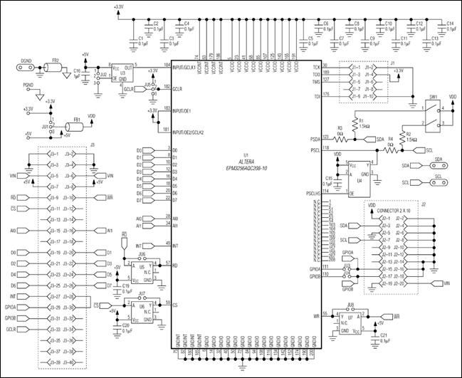
More detailed image (PDF, 841KB)
Figure 4. Configured as shown, the DI2CM IP core in this Altera EPM3256AQC208-10 CPLD implements an I2C Hs-mode master.
The file HSI2C_IP_core_asm.zip contains all the assembly source files needed to implement an Hs-mode I2C master, obtained by interfacing the 68HC16's memory-mapped parallel interface to an Altera EPM3256 CPLD programmed with the DI2CM IP core. The development tool used in this example was the Motorola? 68HC Macro Assembler Version 4.1.
Conclusion
Because the I2C bus is currently the industry's most widely used serial bus, it behooves a system designer to have a handful of proven implementations readily available. The method that you choose—on-chip, bit-banged, or IP-core implementation—depends principally on the system processor. Nonetheless, nothing is easier than using an approach that is proven and already works. This article includes a working reference for each of the three methods.
Appendix 1: Definition of Terms
- CPLD: Complex programmable logic device
- DI2CM: An Hs-mode I2C IP core from Digital Core Design
- FPGA: Field-programmable gate array
- GPI General-purpose input outputs
- hsi2cRecv: Hs-mode I2C receive function, written in assembly language
- Hs-mode: High-speed I2C mode
- IC: Integrated circuit
- IDE: Integrated development environment
- IP: Intellectual property
- I2C: Inter-IC bus
- MAXQ2000: A low-power 16-bit RISC microcontroller
- RS-232: Recommended standard #232
- SCL: Hardware serial-clock line for the I2C bus
- SDA: Hardware serial data line for the I2C bus
- UART: Universal asynchronous receiver-transmitter
- μC: Microcontroller
- 8-N-1: 8 bits, no parity, and 1 stop bit
References
- Philips Semiconductor Staff, "The I2C-Bus Specification," Version 2.1, January 2000. Philips Semiconductor document #9398 393 40011.
- Philips Semiconductor Staff, "The I2C-bus and how to use it," April 1995. Philips Semiconductor document #98-8080-575-01.
- SBS Implementers Forum, "System Management Bus (SMBus) Specification," Version 2.0, August 2000.
- Ted Salazar, in Maxim application note 2394, "Interfacing the MAX1169 ADC to a PIC Microcontroller."
- Ted Salazar, in Maxim application note 3568, "Using the MAXQ2000 with the MAX4397 to Create an Inexpensive Audio/Video Source Selector."
- Maxim application note 3588, "Software I2C Driver for the MAXQ2000 Microcontroller."
- Maxim application note 3561, "Getting Started with MAX-IDE."
- Digital Core Design Staff, "DI2CM I2C Bus Controller Master, HDL Core Specification," Version 2.25.ma.
A similar article was published on the Embedded.com website, August 8, 2007.
Altera is a registered trademark of Altera Corporation.
IAR Embedded Workbench is a registered trademark of IAR Systems AB.
Motorola is a registered trademark of Motorola, Inc.
Philips is a registered trademark of Philips Corp.
PIC is a registered trademark of Microchip Technology, Inc.
SMBus is a trademark of Intel Corp.
 電子發燒友App











評論