本文主要是詳細(xì)講解zybo硬件系統(tǒng)搭建,u-boot,linux-kernel移植,linaro文件系統(tǒng)移植。過程中需要生成的文件有system.bit,fsbl.elf,u-boot.elf,devicetree.dtb,uImage(zImage和uImage區(qū)別請看),linaro文件系統(tǒng)(linaro.org可以下載)
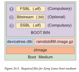
If you are new to linux I would recommend reading through some of the references at the bottom of the page. For this tutorial I am working on a Linux Ubuntu 14.04 vm. Figure 1 is an important overview of the entire design process and how everything comes together to create the necessary components to boot linux on the Zynq-7000 SoC. The end goal of this tutorial is to cover the steps from the beginning stages all the way to booting a Linaro Linux distribution with a graphical user interface on the ZYBO. At this point the tutorial only covers the stages up to booting to a Linaro root shell.
Things you will need!!
1、Xilinx Vivado 2014
2、Xilinx SDK 2014
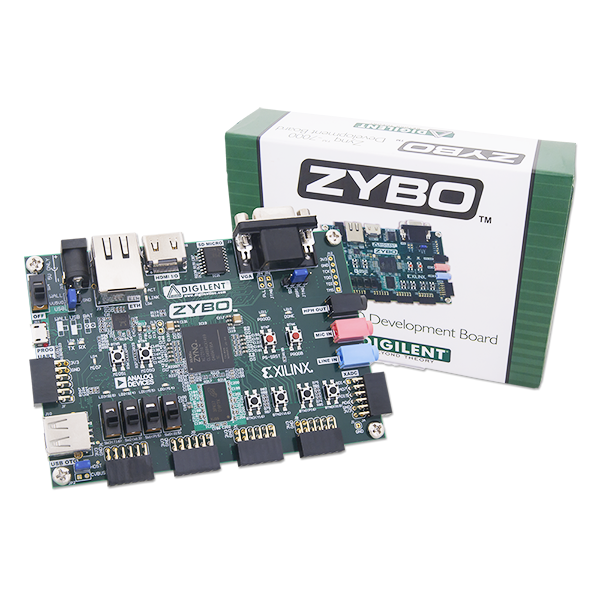
3、Digilent’s ZYBO board
4、Linux-Digilent-Dev master-next branch obtained here.
5、u-boot-Digilent-Dev master-next branch obtained here.
6、 zybo base system( zybo_base_system.zip) here
Step 1: Obtaining necessary files and repositories
I would recommend making a project folder to work from. I am working from zee-bow on the desktop but it is up to you as to where you want to setup. Also create two more folders to put the boot files and root system files as we create them. I named these folders sd_boot and sd_fs.
1) Download the zybo base system from the Digilnets ZYBO product page.
2) Download the Digilent Inc. u-boot-Digilent-Dev and Linux-Digilent-Dev repositories. Make sure to get the master-next branch as these contain the necessary zybo config and dts files. These will be used to create the kernel and u-boot.elf.
Figure 2: Cloning Linux-Digilent-Dev and u-boot-Digilent-Dev into my working folder.
注意:一定要在master-next branch中下載zybo相應(yīng)的配置文件,u-boot和kernel默認(rèn)不包含這些文件的
默認(rèn)DigilentInc/u-boot-Digilent-Dev中boards.cfg文件中也不會包含zybo的配置文件,我們也必須在master-next branches中去下載boards.cfg文件
Step 2: Compiling U-Boot
目的:編譯u-boot,生成u-boot.elf文件
編譯u-boot需要做以下兩部修改:
1、修改環(huán)境變量,使得編譯器GCC指向交叉編譯器xilinx-linux-gnueabi-
目標(biāo)處理器類型為arm
In order to compile the U-Boot and later the kernel we need to set up the tools and extend the $PATH environment variable to find the tools. I would recommend moving the first two exports and the source into your .bashrc so you don’t have to set them again after closing the terminal.
2、修改 u-boot-Digilent-Dev/include/configs/zynq_zybo.h ,刪除圖片中的綠色一行,以此保證啟動(dòng)時(shí)候不會去加載ramdisk,因?yàn)楸疚牟捎玫奈募到y(tǒng)是linaro的桌面ubuntu。
The next step is to configure and compile the U-Boot. Navigate to the u-boot-Digilent-Dev folder in the terminal. before compiling the u-boot we need to change the zynq_zybo.h file to prevent the u-boot from loading the ramdisk. Instead we want it to pass to the root filesystem.
Figure 4: Configure and building U-Boot for ZYBO.
Now lets compile the u-boot. Run make with the specific board zynq_zybo_config file and then run make and the execute and link u-boot should compile.
Figure 5: Configure and building U-Boot for ZYBO.
If you get an error during this step your $PATH environment variable most likely can not find the tools necessary to compile the u-boot. If the u-boot compiled correctly you should see a u-boot in the top level of the u-boot-Digilent-Dev folder. Lets move this to the sd_boot folder and add an elf extenstion. This will be used to generate the BOOT.bin in the following step.
Figure 6: Adding the elf extension to U-Boot.
Step 3: Building the base design(vivado)
第三步是硬件系統(tǒng)的構(gòu)建,原文采用的vivado,我采用的是EDK+SDK,所以這一節(jié)有點(diǎn)不一樣,但是過程是一樣的,生成文件也是一樣的,都是生成system.bit,fsbl,加上step2中生成的u-boot.elf,三個(gè)文件一起生成boot.bin文件。主要是看你習(xí)慣用vivado還是ISE,我偏向于ISE。如果大家想用vivado,那就就按照原文操作,我采用EDK+SDK單獨(dú)講解。
Now on to the base design. Open your chosen version of Vivado, I am working with Vivado 2014.4 and the corresponding SDK. Open the base design project under zybo_base_system/source/vivado/hw/zybo_bsd/zybo_bsd.xpr. If you are using the version that the base design was created with then this next part does not pertain to you and you can go ahead and generate the bitstream. If you are not using the version that it was created on then you will be prompted with an Older Project Version warning and an option to automatically upgrade to the current version. Select okay to automatically upgrade. A second warning will apear saying Vivado no longer uses ‘work’, select okay. The third warning is notify you that some Xilinx IP’s have undergone changes in this version of Vivado, select report ip status. Select the Upgrade Selected at the bottom of the design tool. It will ask if you wish to proceed, select ok.
Figure 7: Upgrading IPs in Vivado 2014.4.
The tool will notify you that there were six critical warning messages, select ok. These will not cause an issue with the system. The next step is to generate the bitstream. There are no implementations available so the tool will ask to launch synthesis and implementation before generating the bitstream, select yes. There will be warnings that appear during the sysnthesis and implementation, select ok do not worry about those for now. I would recommend reading up on some of the references as this may take some time depending on the processing power of your computer. Once the tool has finished you will need to export hardware.
Figure 8: Exporting hardware for SDK.
Include the bitstream when exporting the hardware and then launch the SDK
Figure 9: Include Bitstream when exporting hardware.
Step 3: Building the base design(EDK)
目的:生成system.bit,并到處硬件工程到SDK
下載得到zybo_base_system.zip
打開zybo_base_systemzybo_base_systemsourceisehwsystem.xmp工程(EDK的工程文件),可以看到完整的zybo硬件構(gòu)架,然后點(diǎn)擊Export Design
最后就會將生成的硬件文件導(dǎo)入到SDK中,新建一個(gè)application,Select C and standalone for the target software language and OS platform。
注意:一定要將fsbl中的fsbl_hooks.h文件替換,替換的fsbl_hooks.h文件在 zybo_base_system/source/vivado/SDK/fsbl 中
Step 4: First Stage Boot Loader
目的:創(chuàng)建fsbl應(yīng)用,生成fsbl.elf文件
Once the SDK loads create a new application project. Make sure the hardware platform has selected the hardware you previously exported from Vivado. Select C and standalone for the target software language and OS platform. Name the project fsbl and select next.
Figure 10: New application project specification
Now we will need to modify the fsbl_hooks.c file and set the mac address. Locate the ZYBO specific fsbl_hooks.c file in the zybo_base_system/source/vivado/SDK/fsbl folder and replace the one that was generated in the SDK fsbl project. Once you have replaced the fsbl_hooks clean and build the project. This will generate the fsbl.elf used to create the BOOT.bin in the next step.
Step 5: Building BOOT.bin
目的:由system.bit,fsbl.elf,u-boot.elf生成boot.bin文件
Select create Zynq Boot image under the Xilinx Tools tab. We need to add, in order, the fsbl.elf, system_wrapper.bit, and the u-boot.elf in order to create the BOOT.bin. The fsbl can be found in the zybo_base_system/source/vivado/hw/zybo_bsd/zybo_bsd.sdk/fsbl/debug folder. The system_wrapper.bit can be found in the zybo_base_system/source/vivado/hw/zybo_bsd/zybo_bsd.sdk/system_wrapper_hw_platform_0 folder. In an earlier step we moved the u-boot.elf into a the sd_boot folder. Next specify the output path where you want the BOOT.bin to be generated.
Figure 11: Generating BOOT.bin.
Step 6: Building the Linux kernel
目的:編譯Linux內(nèi)核文件生成uImage
The next step is to build the Linux kernel. Navigate to the Linux-Digilent-Dev folder we downloaded earlier. Now we are ready to compile the kernel. Make sure to run make on the xilinx_zynq_defconfig file to set up the configurations for the zynq chip before compiling the kernel.
Figure 12: Uncompressing the zImage kernel image.
注意:如果這一步出現(xiàn)找不到mkimage工具的錯(cuò)誤,可以在線安裝mkimage
1.sudo apt-get isntall u-boot-tools
Step 7: Generating the Device Tree Blob
目的:編譯設(shè)備樹zynq_zybo.dts,生成zynq_zybo.dtb
Before we generate the device tree blob we need to make some slight adjustments to the zynq_zybo.dts file found Linux-Digilent_dev/arch/arm/boot/dts. Particularly line 44, 53, and 62. changing the clock prevented an error that occured after booting up to the root shell.
Figure 13: Modifying the zynq_zybo.dts.
Now we are ready to generate the dtb file. After this is complete copy it into the sd_boot folder and rename it devicetree.dtb.
Figure 14: Modifying the zynq_zybo.dts.
Step 8: Partitioning your Secure Digital card
目的:采用gparted分區(qū)工具對SD卡進(jìn)行分區(qū)(FAT32+EXT4),將boot.bin,uImage,device.dtb拷貝至fat32中。
There are a couple of ways to do this, the easier way is to use Gparted. A second way is to use the command line tool fdisk. If you do not have gparted it is fairly easy to download and install. Type sudo apt-get install gparted to install it and sudo gparted to run it. Once you have it install plug in your SD card and select it from the drop down window in the top left. If you have any information on the SD card make sure to back it up otherwise select the partition tab and unmount the partition then select and delete the partition. Select the check mark that appears, confirming you wish to delete the partition. Create two new partitions, the first with a beginning offset of 4 MiB. The first partition should be FAT32 and be 1 GiB, the second partition should be ext4 and can take the remaining space.
Figure 15: Partitioning the boot SD card.
Step 9: Obtaining the Linaro file system
目的:在線下載linaro-ubuntu文件系統(tǒng),將解壓后的linaro文件系統(tǒng)拷貝至sd卡中的ext4文件系統(tǒng)中
Download the Linaro file system tar ball from here. We are interested in the last one in the list. Extract the contents and cd into binary/boot/filesystem.dir. Now we need to sync the contents of this folder with the ROOT_FS partition we just created.
Figure 16: Syncing the Linaro root file system with the ROOT_FS partition on the SD card.
Step 10: Booting the ZYBO
Now we need to put BOOT.bin, devicetree.dtb, and uImage onto the FAT32 boot partition. I would recommend creating a temporary folder, mounting the boot partition to that folder, and then using rsync to copy the files over. Once the files are on the correct partition eject the SD card and put it into your ZYBO. Make sure the JP5 jumper is set to SD and JP7 is set to wall. You can boot it from the usb but I would recommend using the wall to power the board. Connect to a uart port terminal, I use GtkTerm to connect to the hardware. It is available in the Ubuntu Software Center, when running it make sure to use sudo as it will need permission to connect to the usb port. Power on the ZYBO and then in the serial port terminal set the configuration to the port where the ZYBO is connected and set the baud rate to 11500, everything else should stay as defualt.
Figure 17: Booting from SD on the ZYBO to the Linaro root shell.
References
[1] Xilinx Getting Started Wiki
[2] Digilent Embedded Linux Hands-on Tutorial for the ZYBO
[3] What-is-Linux
[4] Device Tree Wiki
[5] Initrd Wiki
 電子發(fā)燒友App







評論