Uart 簡介
UART 全稱為 Universal Asynchronous Receiver/Transmitter,譯為通用異步收發(fā)傳輸器。它是一種通用串行數(shù)據(jù)總線,將數(shù)據(jù)在串行通信與并行通信之間進行轉(zhuǎn)換,用于異步通信。
Uart 一般有以下幾個特點:
◆ 可完成數(shù)據(jù)的串并、并串轉(zhuǎn)換;
◆ 可雙向通信,實現(xiàn)全雙工傳輸和接收;
◆ 協(xié)議簡單,最少使用 2 根信號線和一根地線即可完成數(shù)據(jù)收發(fā),但抗干擾能力差;
◆ 傳輸速率低,一般不到 1Mbps。當(dāng)傳輸速率超過 3Mbps 時,收發(fā)波形不均勻,誤碼率高;
◆ 傳輸距離有限,TTL 電平標(biāo)準(zhǔn)下最長可傳輸 3 米左右,RS232 電平標(biāo)準(zhǔn)最長支持傳輸長度為 15 米左右;
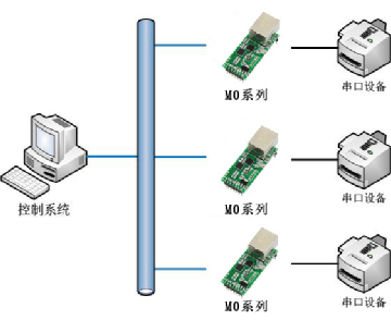
◆ 應(yīng)用廣泛,常用于數(shù)據(jù)采集與通信、電路輔助測試、電路控制等。例如通過 USB/網(wǎng)線轉(zhuǎn)串口模塊,可以時序計算機與串口設(shè)備的連接,串口設(shè)備可以是打印機、開發(fā)板等。
Uart 管腳
Uart 一般使用 9 針的 DB9 接口來完成數(shù)據(jù)終端設(shè)備 (DTE) 與數(shù)據(jù)通訊設(shè)備 (DCE) 之間的數(shù)據(jù)交換。實際 Uart 的 DB9 接口圖如下所示。

如上圖所示,DB9 公頭從左到右、從上倒下,分別對應(yīng)的針管腳標(biāo)號為 1 到 9。各個管腳的功能簡單表述如下表所示。需要注意的是,為了能和公頭相連接,母頭管腳標(biāo)號從右上角開始。

Uart 協(xié)議
Uart 常用的傳輸協(xié)議示意圖如下:

◆ 起始位:為低電平,表示傳輸數(shù)據(jù)的開始。
◆ 數(shù)據(jù)位:近鄰起始位之后,表示要傳輸?shù)臄?shù)據(jù)。數(shù)據(jù)長度可以為 5、6、7、8 ,但經(jīng)常使用的數(shù)據(jù)長度為 8,用于表示一個 ASCII 字符。數(shù)據(jù)從低位到高位依次傳輸。
◆ 奇偶校驗位:數(shù)據(jù)位加上此位數(shù)據(jù)后,使得 “1” 的位數(shù)為偶數(shù) (偶校驗) 或奇數(shù) (奇校驗)。例如,當(dāng)為奇校驗時,如果 8 位數(shù)據(jù)中 1 的數(shù)量為奇數(shù),則此校驗位為 1;如果 8 位數(shù)據(jù)中 1 的數(shù)量為偶數(shù),則此校驗位為 1。偶校驗同理。校驗位也可以去除不傳輸。
◆ 停止位:一針數(shù)據(jù)傳輸結(jié)束的標(biāo)志,可以是 1 位、1.5 位、2 位的高電平。停止位個數(shù)越多,數(shù)據(jù)傳輸越穩(wěn)定,但是數(shù)據(jù)傳輸速度也越慢。
◆ 空閑位:當(dāng)總線處于空閑狀態(tài)時,所有信號線要保持為高電平,表示沒有數(shù)據(jù)傳輸。
Uart 接收時大致的工作過程描述如下:
當(dāng)總線由高電平變?yōu)榈碗娖綍r,表示數(shù)據(jù)開始傳輸。起始位之后可接收到 8 個數(shù)據(jù)位。如果設(shè)置了奇偶校驗功能,可根據(jù)接收的數(shù)據(jù)位和奇偶校驗位進行檢測。校驗出錯,則數(shù)據(jù)丟掉。最后,接收到高電平停止位。如果停止位不為高電平,表示此次傳輸出錯,數(shù)據(jù)也要丟掉。最后總線保持為高電平狀態(tài),表示一次接收完畢。同時,Uart 內(nèi)部將接收到的串行數(shù)據(jù)轉(zhuǎn)換為并行數(shù)據(jù)。
Uart 發(fā)送過程與接收過程類似,這里不再描述。
◆ 波特率
傳輸過程中,1bit 數(shù)據(jù)的傳輸速率用波特率來描述,單位為 bps (bit per second)。一般經(jīng)常使用的波特率都為 9600、19200、115200 等,表示 Uart 每秒傳輸多少比特數(shù)據(jù)。
由于起始位、停止位的存在,實際的傳輸速率并不等于波特率。例如,不考慮校驗位,傳輸 8 位有效數(shù)據(jù)實際需要傳輸 10 位數(shù)據(jù)(8 位數(shù)據(jù)和起始位、停止位),所以實際的數(shù)據(jù)傳輸速率為波特率的 80%。
◆ 誤碼率
當(dāng)傳輸 8bit 真實數(shù)據(jù)時,不考慮校驗位。假如發(fā)送數(shù)據(jù)和接收數(shù)據(jù)都存在誤差,這種誤差可以累加,那么極限情況就是在接收最后 1bit 數(shù)據(jù)的結(jié)束時發(fā)生錯誤。加上已經(jīng)正確傳輸?shù)?19bit 數(shù)據(jù),那么波特率最大誤差為 1/20=5% 。
實際中如果不是連續(xù)傳輸,即 Uart 發(fā)送和接收中間的延遲時間比較長時,那么要求的波特率誤差將會更小。
Uart 實現(xiàn)
◆ 參數(shù)設(shè)計
下面使用 Verilog 設(shè)計一個 Uart 模塊,參數(shù)如下:
波特率:115200
數(shù)據(jù)位寬度:8
校驗位:無
工作時鐘:50 Mhz
◆ 接收模塊
Uart 接收端口說明如下表所示:

Uart 接收數(shù)據(jù)狀態(tài)示意圖如下所示:

(1) 上電后 Uart 進入空閑狀態(tài) S_IDLE ;
(2) 當(dāng)輸入端 rx_pin 變低時,表示傳輸開始,進入開始狀態(tài) S_START ;
(3) 等待 1bit 的時間,進入接收數(shù)據(jù)狀態(tài) S_REC_BYTE ;
(4) 接收完 8bit 數(shù)據(jù)接收后,進入停止?fàn)顟B(tài) S_STOP ;
(5) 停止?fàn)顟B(tài)后增加一個 S_DATA 狀態(tài),用于將接收到的數(shù)據(jù)輸出 ;
(6) 最后回到空閑狀態(tài) S_IDLE,等待下一次接收。
接收代碼描述如下:
module uart_rx
#(
        parameter CLK_FRE = 50,      //clock frequency(Mhz)
        parameter BAUD_RATE = 115200 //serial baud rate
)
(
        input                        clk,              //clock input
        input                        rst_n,            //asynchronous reset input, low active
        output reg[7:0]              rx_data,          //received serial data
        output reg                   rx_data_valid,    //received serial data is valid
        input                        rx_data_ready,    //data receiver module ready
        input                        rx_pin            //serial data input
);
//calculates the clock cycle for baud rate
localparam                       CYCLE = CLK_FRE * 1000000 / BAUD_RATE;
//state machine code
localparam                       S_IDLE      = 1;
localparam                       S_START     = 2; //start bit
localparam                       S_REC_BYTE  = 3; //data bits
localparam                       S_STOP      = 4; //stop bit
localparam                       S_DATA      = 5;


reg[2:0]                         state;
reg[2:0]                         next_state;
reg                              rx_d0;            //delay 1 clock for rx_pin
reg                              rx_d1;            //delay 1 clock for rx_d0
wire                             rx_negedge;       //negedge of rx_pin
reg[7:0]                         rx_bits;          //temporary storage of received data
reg[15:0]                        cycle_cnt;        //baud counter
reg[2:0]                         bit_cnt;          //bit counter


assign rx_negedge = rx_d1 && ~rx_d0;


always@(posedge clk or negedge rst_n) begin
        if(rst_n == 1'b0)
        begin
                rx_d0 <= 1'b0;
                rx_d1 <= 1'b0;
        end
        else
        begin
                rx_d0 <= rx_pin;
                rx_d1 <= rx_d0;
        end
end


always@(posedge clk or negedge rst_n) begin
        if(rst_n == 1'b0)
                state <= S_IDLE;
        else
                state <= next_state;
end


always@(*) begin
        case(state)
                S_IDLE:
                        if(rx_negedge)
                                next_state <= S_START;
                        else
                                next_state <= S_IDLE;
                S_START:
                        if(cycle_cnt == CYCLE - 1)//one data cycle
                                next_state <= S_REC_BYTE;
                        else
                                next_state <= S_START;
                S_REC_BYTE:
                        if(cycle_cnt == CYCLE - 1  && bit_cnt == 3'd7)  //receive 8bit data
                                next_state <= S_STOP;
                        else
                                next_state <= S_REC_BYTE;
                S_STOP:
                        if(cycle_cnt == CYCLE/2 - 1)//half bit cycle,to avoid missing the next byte receiver
                                next_state <= S_DATA;
                        else
                                next_state <= S_STOP;
                S_DATA:
                        if(rx_data_ready)    //data receive complete
                                next_state <= S_IDLE;
                        else
                                next_state <= S_DATA;
                default:
                        next_state <= S_IDLE;
        endcase
end


always@(posedge clk or negedge rst_n) begin
        if(rst_n == 1'b0)
                rx_data_valid <= 1'b0;
        else if(state == S_STOP && next_state != state)
                rx_data_valid <= 1'b1;
        else if(state == S_DATA && rx_data_ready)
                rx_data_valid <= 1'b0;
end


always@(posedge clk or negedge rst_n) begin
        if(rst_n == 1'b0)
                rx_data <= 8'd0;
        else if(state == S_STOP && next_state != state)
                rx_data <= rx_bits;//latch received data
end


always@(posedge clk or negedge rst_n) begin
        if(rst_n == 1'b0)
                begin
                        bit_cnt <= 3'd0;
                end
        else if(state == S_REC_BYTE)
                if(cycle_cnt == CYCLE - 1)
                        bit_cnt <= bit_cnt + 3'd1;
                else
                        bit_cnt <= bit_cnt;
        else
                bit_cnt <= 3'd0;
end


always@(posedge clk or negedge rst_n)
begin
        if(rst_n == 1'b0)
                cycle_cnt <= 16'd0;
        else if((state == S_REC_BYTE && cycle_cnt == CYCLE - 1) || next_state != state)
                cycle_cnt <= 16'd0;
        else
                cycle_cnt <= cycle_cnt + 16'd1;
end


//receive serial data bit data
//避免對串行輸入數(shù)據(jù)的誤采樣,在波特率計數(shù)器的中間值時刻進行采樣
always@(posedge clk or negedge rst_n) begin
        if(rst_n == 1'b0)
                rx_bits <= 8'd0;
        else if(state == S_REC_BYTE && cycle_cnt == CYCLE/2 - 1)
                rx_bits[bit_cnt] <= rx_pin;
        else
                rx_bits <= rx_bits;
end
endmodule
◆ 發(fā)送模塊
Uart 發(fā)送端口說明如下表所示:

Uart 發(fā)送數(shù)據(jù)狀態(tài)示意圖如下所示:

(1) 上電后 Uart 進入空閑狀態(tài) S_IDLE ;
(2) 如果有發(fā)送請求,進入開始狀態(tài) S_START ;
(3) 等待 1bit 的時間,進入發(fā)送數(shù)據(jù)狀態(tài) S_SEND_BYTE ;
(4) 發(fā)送完 8bit 數(shù)據(jù)接收后,進入停止?fàn)顟B(tài) S_STOP ;
(5) 最后回到空閑狀態(tài) S_IDLE,等待下一次數(shù)據(jù)發(fā)送。
發(fā)送模塊代碼描述如下:
module uart_tx
#(
        parameter CLK_FRE = 50,      //clock frequency(Mhz)
        parameter BAUD_RATE = 115200 //serial baud rate
)
(
        input                        clk,              //clock input
        input                        rst_n,            //asynchronous reset input, low active
        input[7:0]                   tx_data,          //data to send
        input                        tx_data_valid,    //data to be sent is valid
        output reg                   tx_data_ready,    //send ready
        output                       tx_pin            //serial data output
);
//calculates the clock cycle for baud rate
localparam                       CYCLE = CLK_FRE * 1000000 / BAUD_RATE;
//state machine code
localparam                       S_IDLE       = 1;
localparam                       S_START      = 2;//start bit
localparam                       S_SEND_BYTE  = 3;//data bits
localparam                       S_STOP       = 4;//stop bit
reg[2:0]                         state;
reg[2:0]                         next_state;
reg[15:0]                        cycle_cnt; //baud counter
reg[2:0]                         bit_cnt;//bit counter
reg[7:0]                         tx_data_latch; //latch data to send
reg                              tx_reg; //serial data output
assign tx_pin = tx_reg;
always@(posedge clk or negedge rst_n) begin
        if(rst_n == 1'b0)
                state <= S_IDLE;
        else
                state <= next_state;
end


always@(*) begin
        case(state)
                S_IDLE:
                        if(tx_data_valid == 1'b1)
                                next_state <= S_START;
                        else
                                next_state <= S_IDLE;
                S_START:
                        if(cycle_cnt == CYCLE - 1)
                                next_state <= S_SEND_BYTE;
                        else
                                next_state <= S_START;
                S_SEND_BYTE:
                        if(cycle_cnt == CYCLE - 1  && bit_cnt == 3'd7)
                                next_state <= S_STOP;
                        else
                                next_state <= S_SEND_BYTE;
                S_STOP:
                        if(cycle_cnt == CYCLE - 1)
                                next_state <= S_IDLE;
                        else
                                next_state <= S_STOP;
                default:
                        next_state <= S_IDLE;
        endcase
end


always@(posedge clk or negedge rst_n) begin
        if(rst_n == 1'b0)
                begin
                        tx_data_ready <= 1'b0;
                end
        else if(state == S_IDLE)
                if(tx_data_valid == 1'b1)
                        tx_data_ready <= 1'b0;
                else
                        tx_data_ready <= 1'b1;
        else if(state == S_STOP && cycle_cnt == CYCLE - 1)
                        tx_data_ready <= 1'b1;
end


always@(posedge clk or negedge rst_n) begin
        if(rst_n == 1'b0)
                begin
                        tx_data_latch <= 8'd0;
                end
        else if(state == S_IDLE && tx_data_valid == 1'b1)
                        tx_data_latch <= tx_data;
end


always@(posedge clk or negedge rst_n) begin
        if(rst_n == 1'b0)
                begin
                        bit_cnt <= 3'd0;
                end
        else if(state == S_SEND_BYTE)
                if(cycle_cnt == CYCLE - 1)
                        bit_cnt <= bit_cnt + 3'd1;
                else
                        bit_cnt <= bit_cnt;
        else
                bit_cnt <= 3'd0;
end


always@(posedge clk or negedge rst_n) begin
        if(rst_n == 1'b0)
                cycle_cnt <= 16'd0;
        else if((state == S_SEND_BYTE && cycle_cnt == CYCLE - 1) || next_state != state)
                cycle_cnt <= 16'd0;
        else
                cycle_cnt <= cycle_cnt + 16'd1;
end


always@(posedge clk or negedge rst_n) begin
        if(rst_n == 1'b0)
                tx_reg <= 1'b1;
        else
                case(state)
                        S_IDLE,S_STOP:
                                tx_reg <= 1'b1;
                        S_START:
                                tx_reg <= 1'b0;
                        S_SEND_BYTE:
                                tx_reg <= tx_data_latch[bit_cnt];
                        default:
                                tx_reg <= 1'b1;
                endcase
end


endmodule
◆ Uart 模塊整合
將收發(fā)模塊進行整合,組成一個完整的 Uart 模塊。
module uart #(
        parameter CLK_FRE = 50,
        parameter BAUD_RATE = 115200
       )
       (
        input               clk,
        input               rst_n,
        input               rx,
        input               rx_ready,
        output [7:0]        rx_data,
        output              rx_data_valid,


        input [7:0]         tx_data,
        input               tx_data_valid ,
        output              tx ,
        output              tx_ready
        );


   uart_rx #(
      .CLK_FRE(CLK_FRE),
      .BAUD_RATE(BAUD_RATE))
   u_rx(
        .clk                (clk           ),
        .rst_n              (rst_n         ),
        .rx_pin             (rx            ), //input
        .rx_data_ready      (rx_ready      ),
        .rx_data            (rx_data       ), //output
        .rx_data_valid      (rx_data_valid )
        );


   uart_tx  #(
       .CLK_FRE(CLK_FRE),
       .BAUD_RATE(BAUD_RATE))
   u_tx (
         .clk               (clk           ),
         .rst_n             (rst_n         ),
         .tx_data           (tx_data       ), //input
         .tx_data_valid     (tx_data_valid ),
         .tx_pin            (tx            ), //output
         .tx_data_ready     (tx_ready      )
         );
endmodule
◆ Testbench
Uart 測試時采用自回環(huán)的測試方法,即 Uart 發(fā)送端接口與接收端接口相連,實現(xiàn)自發(fā)自收。此測試方法簡單且有效。
`timescale 1ns/1ns
module test;


   //clock and reset
   reg clk;
   always #10 clk = ~clk ;


   reg rstn ;
   initial begin
      rstn      = 0 ;
      clk       = 0 ;
      # 4.5 ;
      rstn      = 1 ;
   end


   reg [7:0]    tx_data ;
   reg          tx_data_valid ;
   wire [7:0]   rx_data ;
   wire         rx_data_valid ;
   wire         tx2rx, tx2rx_ready;


   //test in loop
   uart u_uart1  (
        .clk            (clk),
        .rst_n          (rstn),
        .rx             (tx2rx),         //in
        .rx_ready       (tx2rx_ready),
        .rx_data        (rx_data[7:0]), //out
        .rx_data_valid  (rx_data_valid),


        .tx_data        (tx_data[7:0]),    //in,
        .tx_data_valid  (tx_data_valid),
        .tx             (tx2rx),              //out
        .tx_ready       (tx2rx_ready)
   );


   initial begin
      tx_data           = 0 ;
      tx_data_valid     = 0 ;
      #100;


      //send data
      wait (tx2rx_ready);
      @(negedge clk);
      tx_data           = 8'h35 ;
      tx_data_valid     = 1 ;
      @(negedge clk);
      tx_data_valid     = 0 ;
      repeat(15) begin
         @(negedge clk);
      end


      wait (tx2rx_ready);
      @(negedge clk);
      tx_data           = 8'h18 ;
      tx_data_valid     = 1 ;
      @(negedge clk);
      tx_data_valid     = 0 ;
      repeat(15) begin
         @(negedge clk);
      end


      wait (tx2rx_ready);
      @(negedge clk);
      tx_data           = 8'ha6 ;
      tx_data_valid     = 1 ;
      @(negedge clk);
      tx_data_valid     = 0 ;
      repeat(15) begin
         @(negedge clk);
      end
      #100 ;
   end // initial begin


   //receive parallel data
   reg [1:0] rx_data_valid_r ;
   always @(posedge clk or negedge rstn) begin
      if (!rstn) begin
         rx_data_valid_r <= 1'b0 ;
      end
      else begin
         rx_data_valid_r <= {rx_data_valid_r[0], rx_data_valid} ;
      end
   end
   wire rx_data_valid_pos = rx_data_valid_r == 2'b01 ;


   reg [7:0]    check_data ;
   integer      check_num ;
   always @(posedge clk or negedge rstn) begin
      if (!rstn) begin
         check_data <= 'b0 ;
         check_num  <= 'b0 ;
      end
      else if(rx_data_valid_pos === 1'b1) begin
         check_data <= rx_data ;
         check_num  <= check_num + 1'b1 ;
      end
   end


   //check 3 byte data
   initial begin
      #1 ;
      forever begin
         @(negedge clk) ;
         if (check_num == 1) begin
            if (check_data !== 8'h35) begin
               $display("---III--- 1st data Failed: %h", check_data);
            end
         end
         else if (check_num == 2) begin
            if (check_data !== 8'h18) begin
               $display("---III--- 2nd data Failed: %h", check_data);
            end
         end
         else if (check_num == 3) begin
            if (check_data !== 8'ha6) begin
               $display("---III--- 3rd data Failed: %h", check_data);
               $display("---III--- It's a FAILURE!!!");
            end
            else begin
               #1000000 ;
               $display("---III--- It's a SUCCESS!!!");
               $display("");
               $display("");
            end
            $finish ;
         end
      end // forever begin
   end // initial begin


endmodule
仿真中的自檢驗成功截圖如下所示。

仿真波形圖如下所示。
由圖可知,波特率、首發(fā)數(shù)據(jù)均正確。

 電子發(fā)燒友App






評論