Overview
Programmers commonly use lookup tables in application code when working with microcontrollers. Because of the nature of the MAXQ core, however, application software cannot read directly from code space and, therefore, cannot directly access any tables defined within the application code. To alleviate this issue, all MAXQ microcontrollers implement what is called a "pseudo von Neumann" architecture: developers can store data and tables in program space, but only by using special Utility ROM routines. Besides these core functions, the ROM for each MAXQ microcontroller can have routines specific to that device. This application note describes the steps one must take with the IAR Embedded Workbench to access these Utility ROM functions from code.Specifying the Function Addresses and Prototypes
The first step in utilizing the ROM functions is determining where these functions are located. The User's Guide Supplement for MAXQ devices lists the Utility ROM user functions, their addresses, inputs, and outputs. Use this information to find the entry points for the functions that you will be calling. As an example, Table 1 below (Table 48 from the MAXQ2000 supplement) shows that the flashWrite function is located at word address 08461h.Table 1. Utility ROM User Functions (for Utility ROM Version 1.01)
| FUNCTION NUMBER | FUNCTION NAME | ENTRY POINT | SUMMARY |
| 0 | flashWrite | 08461h | Programs a single word of flash memory. |
| 1 | flashErasePage | 08467h | Erases (programs to FFFFh) a 256-word sector of flash memory. |
| 2 | frashEraseAll | 08478h | Erases (programs to FFFFh) all flash memory. |
| 3 | moveDP0 | 08487h | Reads a byte/word at DP[0] |
| 4 | moveDP0inc | 0848Ah | Reads a byte/word at DP[0], then increments DP[0]. |
| 5 | moveDP0dec | 0848Dh | Reads a byte/word atDP[0], then decrements DP[0]. |
| 6 | moveDP1 | 08490h | Reads a byte/word at DP[1]. |
| 7 | moveDP1inc | 08493h | Reads a byte/word at DP[1], then increments DP[0]. |
| 8 | moveDP1dec | 08496h | Reads a byte/word at DP[1], then decrements DP[0]. |
| 9 | moveFB | 08499h | Reads a byte/word at BP[Offs]. |
| 10 | moveFPinc | 0849Ch | Reads a byte/word at BP[Offs], then increments Offs. |
| 11 | moveFPdec | 0849Fh | Reads a byte/word at BP[Offs], then decrements Offs. |
| 12 | copyBuffer | 084A2h | Copies LC[0] values from DP[0] to BP[Offs]. |
Now that the entry points for the various functions are known, the IAR Embedded Workbench can be configured to use these addresses. Select Options from the Project menu. In the dialog box that appears, select Linker from the Category list. Click on the Extra Options tab and make sure the box labeled "Use command line options" is checked. In the list of options, you must add an item for every Utility ROM function that you intend to use; specify the address of that function. The options should have the following format:
-DThe=
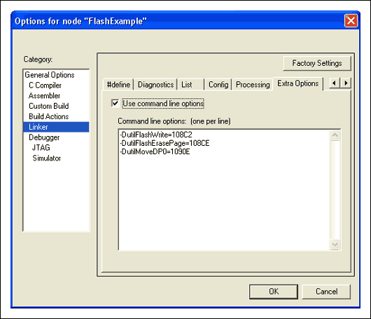
Figure 1. A MAXQ2000 project example uses three ROM functions.
To make these functions accessible through your application code, declare prototypes for each one, using the same names as you specified in the Options screen. The parameter passing is discussed in the following section, so for now declare each prototype as accepting no arguments and having no return value.
extern void utilFlashWrite(void);
extern void utilFlashErasePage(void);
extern void utilMoveDP0(void);
Creating Wrapper Functions
It is now possible to call the ROM functions directly from application code. There is, however, a caveat. Since the functions usually accept their input parameters in registers different from those used by IAR's compiler, the functions could destroy registers upon which the compiler depends. The functions may also need to execute with interrupts disabled. Consequently, you should create some helper functions to handle these issues. For each ROM function that you want to call, determine: what inputs it accepts; the outputs it provides; and the registers it destroys. All of this information can be found in the User's Guide Supplement for your MAXQ device.Continuing our example from above, you can see that the flashErasePage function for the MAXQ2000 has the following description:
Function: flashErasePage
Summary: Erases (programs to 0FFFFh) a 265-word page of flash memory.
Inputs: A[0]: Word address located in the page to be erased. (The page number is the high byte of A[0].)
Outputs: Carry: Set on error and cleared on success.
Destroys: PSF, LC[1], GR, AP, APC
Notes:
- If the watchdog reset function is active, it should be disabled before calling this function.
- When calling this function from flash, care should be taken that the return address is not in the page that is being erased.
With this information you can create a helper function that calls flashErasePage. Besides actually calling the Utility ROM function, this helper function needs to perform four additional steps:
- Configure the input to the ROM function.
- Save and restore any of the reserved registers that the ROM function destroys.
- Process the ROM function's output.
- Save, disable, and restore interrupts around the call to the ROM function.
Preparing the Inputs
This example ROM function accepts A[0] as its input, and setting A[0] is straightforward. We can declare a variable for any register in the MAXQ by using some IAR keywords and macros. To declare a variable for A[0], add the following statement:__no_init volatile __io unsigned int A0 @ _M(0x09,0x00);Pay special attention to the data type and inputs to the _M macro. This variable, A0, was declared as "unsigned int" because it is a 16-bit register. If it were an 8-bit register, we could have declared it as an "unsigned char." The inputs to the _M macro are the module number followed by offset of the A[0] register. Now you can simply set this variable to the value you want in A[0].
A0 = pageAddr;
Preserving Special Registers
You must be careful when using registers in the above manner because the compiler expects certain registers not to change from one function call to the next. The MAXQ IAR C Compiler Reference Guide lists the following registers (Table 2) as scratch registers. You can destroy these registers without disturbing the program flow. Also, the APC and DP[1] registers and bits 0, 1, and 3 of the DPC register should not be modified at any time. If any other registers are changed by a function, they should be restored before exiting that function.Table 2. Scratch Registers1
| MAXQ10 Devices | MAXQ20 Devices |
| A[0], A[1], A[2], A[3], GR, LC[0], LC[1], DP[0], BP, OFFS, AP | A[0], A[1], A[2], A[3], A[4], A[5], A[6], A[7], GR, LC[0], LC[1], DP[0]. BP, OFFS, AP |
The flashErasePage description lists APC as one of the registers destroyed, so you must make sure to save and restore that register before calling utilFlashErasePage. This task is also straightforward if you use IAR's asm() function. MAXQ assembly statements can be inserted directly into C code using this function. Since APC needs to be saved, you can just add asm("push APC") and asm("pop APC") statements around the call to utilFlashErasePage.
Processing the ROM Function's Output
Handling the return from the ROM function is similar to handling the inputs. You can just read the appropriate registers directly. The flashErasePage function, for example, sets the carry bit on an error. You can access this bit directly using the PSF_bit structure declared in the iomaxq.h header file provided by IAR.return (PSF_bit.C == 0);
Saving, Disabling, and Restoring Interrupts
The last task to consider is whether interrupts need to be disabled. Most Utility ROM routines assume that they will not be interrupted. Therefore, if your application uses interrupts, it is wise to disable them before calling the Utility ROM functions. The easiest way to disable them is by using the IC_bit structure defined in the iomaxq.h header file and the __disable_interrupt() function defined in the intrinsics.h file.unsigned char origIGE = IC_bit.IGE; // Save current state. __disable_interrupt(); /* Add UROM call code here. */ IC_bit.IGE = origIGE; // Restore interrupt state.If you follow all of these steps, you will have code that looks similar to the following:
#include#include // Prototype for the real Utility ROM function. extern void utilFlashErasePage(void); // Define the register we need direct access to. __no_init volatile __io unsigned int A0 @ _M(0x09,0x00); unsigned char flashErasePage(unsigned int page) { unsigned int pageAddr; unsigned char origIGE; pageAddr = page << 8; // Change page # to an address. origIGE = IC_bit.IGE; // Save current state. __disable_interrupt(); A0 = pageAddr; // Set up input to UROM function. asm("push APC"); // UROM function destroys APC. utilFlashErasePage(); // Call actual UROM function. asm("pop APC"); // Restore APC. IC_bit.IGE = origIGE; // Restore interrupt state. return (PSF_bit.C == 0); // Check return code from UROM. }
Conclusion
Using the procedures outlined above, you can easily call the functions provided in the Utility ROM of each MAXQ microcontroller. You can create function wrappers that leverage the code in the MAXQ Utility ROM to access lookup tables, store data in program space, and other functions unique to each of the MAXQ family of devices.1At the time this application note was written, the MAXQ IAR C Compiler Reference Guide lists the DPC register as a scratch register. This is an error in the documentation and the DPC register should be considered one of the special registers.
IAR Embedded Workbench is a registered trademark of IAR Systems AB.
MAXQ is a registered trademark of Maxim Integrated Products, Inc.
 電子發(fā)燒友App







評(píng)論