Abstract: This application note describes the use of a current-sense amplifier to monitor the load current of a circuit supply voltage. When the current being drawn from the supply exceeds the predetermined level, an external pass transistor opens up to remove the load from the supply. A separate external transistor crowbars the input to the load to prevent overvoltage. The OFF state is latched until the circuit is reset manually.
CMOS interface ICs serve as gateways to the wired connections between electronic systems. If those external connections are mishandled, the interface ICs can be damaged by a short to ground or by applied voltage that causes them to latch up. For short periods, however, short circuits and latchups are generally safe. (Latchups can be triggered by pulling the gate terminal below ground or above VCC.)
In Figure 1, IC1 monitors supply current to the interface circuitry (IS), and quickly removes current and voltage from the interface if IS exceeds a programmed threshold. During normal operation, IC1's OUT current (1/2000 of IS) flows through R3 to a logic-low level—the output of IC2's lower NOR gate.
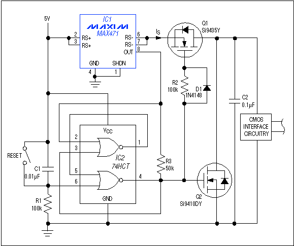
Figure 1.By blocking the supply current and crowbarring the supply voltage, this circuit protects the interface circuitry against faults involving the external lines.
During a fault condition (defined as IS > 50mA by the R3 value shown), the rising OUT current develops 1.2V across R3, causing the set/reset flip-flop (IC2) to produce a low-to-high transition at pin 4. This action shuts down the interface: Q1 blocks the interface supply current, and Q2 "crowbars" the interface supply to prevent overvoltage. Without the crowbar, an external overvoltage fault could act through parasitic diodes in Q1 and the interface IC to lift the main supply voltage. (A positive supply voltage tends to rise if the supply is asked to sink current.)
R3's connection to the flip-flop output instead of ground (as in most MAX471 circuits) introduces hysteresis in the control of Q1 and Q2. Otherwise, oscillation can result: turning off Q1 removes fault current, and the circuit tries to resume normal operation. R2 and D1 provide a break-before-make action that prevents Q1 and Q2 from shorting the supply rails. Once tripped, the circuit remains latched until manually reset with S1.
An LED with current-limiting resistor can be connected as a fault indicator between the main supply and the Q1-Q2 node. Other add-on features include a capacitor across R3 to provide a "slow-blow effect," and the use of a precision reference and comparator (such as the MAX931) for greater accuracy in sensing the R3 voltage.
A similar idea appeared in the 4/25/96 issue of EDN.
CMOS interface ICs serve as gateways to the wired connections between electronic systems. If those external connections are mishandled, the interface ICs can be damaged by a short to ground or by applied voltage that causes them to latch up. For short periods, however, short circuits and latchups are generally safe. (Latchups can be triggered by pulling the gate terminal below ground or above VCC.)
In Figure 1, IC1 monitors supply current to the interface circuitry (IS), and quickly removes current and voltage from the interface if IS exceeds a programmed threshold. During normal operation, IC1's OUT current (1/2000 of IS) flows through R3 to a logic-low level—the output of IC2's lower NOR gate.

Figure 1.By blocking the supply current and crowbarring the supply voltage, this circuit protects the interface circuitry against faults involving the external lines.
During a fault condition (defined as IS > 50mA by the R3 value shown), the rising OUT current develops 1.2V across R3, causing the set/reset flip-flop (IC2) to produce a low-to-high transition at pin 4. This action shuts down the interface: Q1 blocks the interface supply current, and Q2 "crowbars" the interface supply to prevent overvoltage. Without the crowbar, an external overvoltage fault could act through parasitic diodes in Q1 and the interface IC to lift the main supply voltage. (A positive supply voltage tends to rise if the supply is asked to sink current.)
R3's connection to the flip-flop output instead of ground (as in most MAX471 circuits) introduces hysteresis in the control of Q1 and Q2. Otherwise, oscillation can result: turning off Q1 removes fault current, and the circuit tries to resume normal operation. R2 and D1 provide a break-before-make action that prevents Q1 and Q2 from shorting the supply rails. Once tripped, the circuit remains latched until manually reset with S1.
An LED with current-limiting resistor can be connected as a fault indicator between the main supply and the Q1-Q2 node. Other add-on features include a capacitor across R3 to provide a "slow-blow effect," and the use of a precision reference and comparator (such as the MAX931) for greater accuracy in sensing the R3 voltage.
A similar idea appeared in the 4/25/96 issue of EDN.
 電子發燒友App





評論