Abstract: Charge NiCd or NiMH batteries with solar cells. This circuit extracts the maximum power from a solar array to charge a battery stack. It employs the MAX856 boost converter and MAX982 dual comparator with reference.
Additional Information:
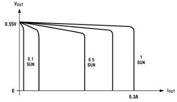
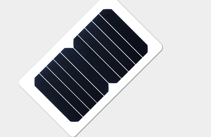
The output current for typical monocrystalline-silicon solar cells directly depends on the amount of incident sunlight (Figure 1). For example, a typical hobby-grade credit-card-sized silicon cell has an open-circuit voltage of 0.55V. Internal resistance causes a voltage drop as you draw current from the cell; but, as light energy drops below the level necessary to support the output load, the cell current-limits at an almost constant voltage. For a light level of one full sun (solar irradiance of 1kW/m2), the cell provides a typical short-circuit current of 0.3A.
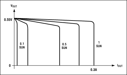
Figure 1. Available current output from a solar cell is proportional to the incident-light energy, but the cell's open-circuit voltage is almost constant.
Maximum output power arises at the transition from constant voltage to constant current, typically 0.484V and 0.25 to 0.275A at one full sun. This 0.484V is too low for most applications, so solar panels usually connect the cells in a series/parallel combination that provides several amperes of current at about 12V. Such outputs are useful for many applications, assuming full sunlight is available whenever the application is active. Unfortunately, this imperative is hard to realize in most locations. Varying sunlight has less effect on the open-circuit voltage but has a direct effect on the maximum available current (Figure 1). This characteristic is critical in designing electronics that optimize the use of the power available at any given time.
Most applications include an intermediate energy-storage device, such as a rechargeable lead-acid or nickel-cadmium (NiCd) battery, to ensure an always-ready source of power. When light is sufficient, the solar cell charges the battery, which then provides the load with a stable supply. Charging the battery directly from the solar panel (via a series diode) is difficult or at least inefficient, because battery voltage changes considerably as the battery charges.
Obtaining all the available energy from a solar panel requires a switch-mode step-up or -down converter and battery charger, in addition to the battery. The converter must ensure that every bit of energy taken from the solar panel is efficiently stored in the battery for future use. A switch-mode converter works in two cycles. It first connects an inductor to a power source, allowing a buildup of inductor current that stores energy in the inductor. In the second cycle, a change in current path enables the inductor to transfer its accumulated energy to the load. The load voltage can be higher or lower than that of the inductor's power source.
Connecting the inductor directly to a solar panel is inefficient. Depending on light levels, the panel's output-current capability can range from microamps to several amperes. A much better approach is to connect a reservoir capacitor to the solar panel. By monitoring voltage on this capacitor, you can then turn on the switch-mode converter only when the panel output is optimum, that is, 0.484V times the number of (ranks of) series-connected cells in the panel. This input is adequate to start the converter, and the capacitor provides a low-impedance path for the inductor current. Moreover, the capacitor supports full cycles of converter operation without allowing the converter's input voltage to drop below its operating voltage. When the capacitor voltage drops below a predetermined level (the converter's minimum operating voltage or higher), the converter shuts down until the capacitor again charges to the optimum voltage.
In Figure 2, a comparator with hysteresis controls the converter's shutdown pin. As long as the reservoir capacitor's voltage is lower than the optimum load voltage for the solar panel (0.484V times the series-connected-cell number), the converter is in shutdown. When the capacitor voltage reaches this optimum load voltage, the converter is enabled until the capacitor voltage declines to the lower limit of the comparator's hysteresis band.
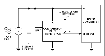
Figure 2. The input to a DC/DC converter for solar-panel power conversion comprises the panel, a reservoir capacitor, and a comparator/reference circuit that enables the converter only when adequate power is available.
Operating in bursts whenever there is sufficient charge on the capacitor, the converter charges the battery only when the value of reservoir-capacitor voltage is optimum for all levels of sunlight. In effect, the solar panel's load (the switch-mode converter) adjusts automatically to the solar panel's best operating area (its V/I limit). The ratio of solar-panel no-load voltage to battery voltage determines whether the converter action must step up or step down.
If the solar-panel no-load voltage (determined by the number of series-connected cells) is lower than the voltage of the discharged battery, choose a step-up converter. If the panel voltage under load is higher than that of the fully charged battery, choose a step-down converter. Otherwise, rearrange the number of battery or solar cells to find a combination of battery and solar panel that satisfies one of those conditions.
Step-down converters have no direct path from input to output during shutdown, but the step-up configuration has a DC path (via the inductor and output diode) at all times, including shutdown. Be aware that step-up converters have no current limit in the event of a shorted output. The solar panel is current-limited, so the main worry in such cases is probably a shorted battery, which may require other means of circuit protection.
Terminating a fast charge is difficult for at least two reasons. After reaching a certain battery voltage, the above burst-conversion scheme does not hint at when the next conversion cycle will occur. If it occurs within milliseconds, you should probably stop the fast charge. If it occurs within hours or days (when sunlight is scarce), the fast charge should continue, because the battery can otherwise drain long before the next cycle. The other difficulty stems from charge current arriving in infrequent bursts: You can't detect a zero or negative dV/dt under this condition.
One approach applicable to both lead-acid and NiCd batteries is to monitor the output voltage with another comparator, disabling switching when the voltage reaches a high limit and enabling it when the voltage declines below a predetermined level. A third level of detection could also enable a float-current (trickle) charge of the battery (Figure 3). When charging a discharged battery, the circuit applies full fast-charge current until the voltage reaches its upper limit. The circuit then disables switching until the voltage reaches the next-lowest (middle) limit, whereupon it enables the trickle charge. Trickle charging continues until the voltage reaches its upper limit (turning off the switching) or its lower limit (enabling the fast charge again).
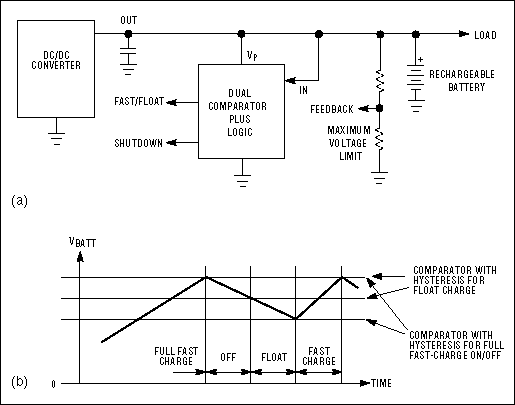
Figure 3. The DC/DC converter enables a solar panel to charge a rechargeable battery (a). Comparator-generated signals enable the circuit to control the charging current (b).
A dual comparator with hysteresis controls the converter shutdown and the selection of fast charge versus trickle charge. To prevent discharge of the battery when the solar-panel voltage goes to zero, you should design the comparator circuit not to load the battery via its supply terminal or the external resistive divider. You can control the converter shutdown from either the output comparator or the input comparator when solar-panel voltage is low, and this capability may require additional logic.
The circuit in Figure 4, which charges a three-cell battery from a seven-cell solar panel, illustrates the above ideas. The battery voltage at discharge is greater than 3.0V, and the optimum solar-panel output is 2.9V (3.8V maximum), so the circuit requires converter (IC1). The dual comparator controls shutdown and charge termination. IC2A directly controls shutdown, holding the converter in shutdown until the solar panel charges C1 to 2.9V. The converter then becomes active, and hysteresis allows the operation to continue until the voltage drops below 2.5V. While on, the converter delivers its full output current, subject only to the internal current limit.
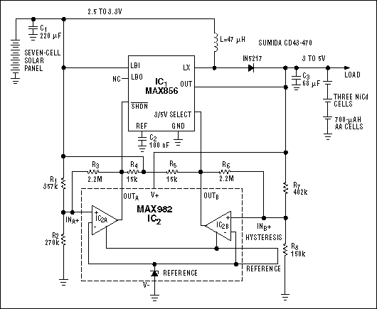
Figure 4. This circuit enables a seven-cell solar panel to charge a three-cell NiCd battery.
Regulation first begins when the battery voltage reaches 5.0V, but the output comparator (IC2B) terminates the charge cycle at 4.6V. The design handles termination not by controlling the shutdown pin, which requires additional logic, but by the unconventional approach of driving the 3/5V-select pin high. Because the output is at 4.6V, selecting a 3V output (actually 3.3V) causes the converter to turn off. Again, comparator hysteresis ensures that the converter remains off until the battery voltage decreases to 4V. It then resumes operation, providing a simple form of idle charging that does not overcharge the battery.
Because the converter shuts down when the solar-panel output is low, the battery-discharge current (the sum of converter-shutdown current, comparator-supply current, R7/R8 current, and reverse current from the Schottky diode) is minimal. The Schottky reverse current is 5μA typical at 25°C and 50μA or higher at 50°C, which is too high for some applications. For those, you can substitute a switching diode, such as the 1N4148, at the expense of slightly lower converter efficiency. You should avoid taking the output lower than the input, as with all step-up converters. In this case, an overload or shorted battery cell can cause an uncontrolled DC current flow from the solar panel through the inductor and diode to the output. In most cases, however, current limiting in the solar panel allows the battery to simply recharge to 3V without damage to the inductor.
Applications in which the solar-panel voltage is lower than the low-battery voltage require a step-up converter, and applications that need more current (or a peak current other than that determined by the fixed internal setting) require a step-up controller. Applications in which the solar-panel voltage is higher than the fully charged battery voltage demand a step-down converter. As an example of applications demanding a step-down converter, configuring the MAX797 controller as a current source and its internal 5V linear regulator can power the external comparators. The device is well suited for charging a car battery from two 12V solar panels.
These circuits and techniques should ensure efficient battery charging from solar panels despite unpredictable weather conditions. The target applications are primarily low to medium power, from a few watts to 100W. A further refinement in the charger circuit, though not required for most NiCd and lead-acid batteries, could sense the battery current and use that information to provide a constant current-source output with voltage limit.
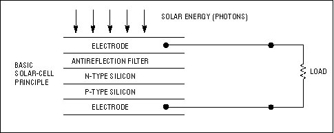
Figure A. Light energy on a solar cell generates charge carriers that flow in an external circuit.
Irradiating a silicon pn junction with photons of energy greater than the bandgap of silicon produces hole-electron pairs. For reverse-biased junctions, the pairs generated within a diffusion length of the depletion region separate from each other and contribute to photocurrent in the external circuit. For an unbiased junction, this charge separation in the junction's internal field produces a forward bias on the junction. Such a device is called a photovoltaic cell. Photovoltaic cells that obtain electrical power from sunlight are called solar cells.
Solar-cell efficiency (photon-to-electron conversion) depends on the fraction of light reflected from the surface, the fraction absorbed before reaching the junction, and the fraction that produces useful hole-electron pairs separated by the junction. Silicon is commonly used for commercially available solar cells, with typical efficiencies from 3% to 15%.
Solar cells are classified by their material: either silicon in its crystalline or amorphous form, or the compound semiconductors, which in turn are classified according to element groups in the periodic table (II to VI group, III to V group, others) (Figure B).
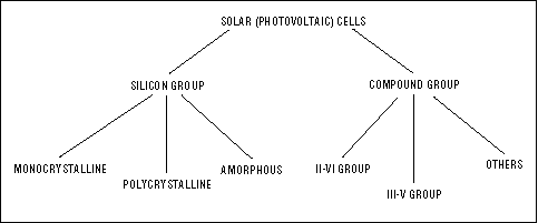
Figure B. Manufacturers fabricate solar cells from various forms of silicon and from the compound-semiconductor materials.
Monocrystalline-silicon solar cells have a theoretical efficiency of about 30%, and efficiencies greater than 20% have been achieved under laboratory conditions. Amorphous silicon, unlike the crystalline or polycrystalline forms, has a noncrystalline structure in which the atoms have no regular pattern of arrangement. Amorphous-silicon solar cells are not as efficient, but they require less silicon and less manufacturing energy, and manufacturers can produce them with larger surface areas. These attributes may lead to inexpensive amorphous solar cells in the future. Another candidate for low cost and high efficiency is the thin-film polycrystalline-silicon solar cell, which forms by heating amorphous silicon to recrystallize it.
Scientists have developed various thin-film and sintering technologies to support the investigation of compound materials, such as CdTe and CuInSe2, as candidate materials for mass-produced solar cells. Conversion efficiencies for these materials range from 13% to 25%.
To make the solar cell an economical alternative to other methods of power generation, manufacturers have directed much research and refinement of production methods toward increasing the solar cell's efficiency. Recent improvements are promising, but so far engineers use solar power mainly for single applications with modest requirements: remote communications equipment, nautical beacons and lighting, emergency power, and, in a few cases, the local electricity supply.
A similar version of this article appeared in the February 4, 1999 issue of EDN.
Additional Information:
- Quick View Data Sheet for the MAX856
- Quick View Data Sheet for the MAX982
- Samples and Literature Order Form
- Technical Support: Power
The output current for typical monocrystalline-silicon solar cells directly depends on the amount of incident sunlight (Figure 1). For example, a typical hobby-grade credit-card-sized silicon cell has an open-circuit voltage of 0.55V. Internal resistance causes a voltage drop as you draw current from the cell; but, as light energy drops below the level necessary to support the output load, the cell current-limits at an almost constant voltage. For a light level of one full sun (solar irradiance of 1kW/m2), the cell provides a typical short-circuit current of 0.3A.

Figure 1. Available current output from a solar cell is proportional to the incident-light energy, but the cell's open-circuit voltage is almost constant.
Maximum output power arises at the transition from constant voltage to constant current, typically 0.484V and 0.25 to 0.275A at one full sun. This 0.484V is too low for most applications, so solar panels usually connect the cells in a series/parallel combination that provides several amperes of current at about 12V. Such outputs are useful for many applications, assuming full sunlight is available whenever the application is active. Unfortunately, this imperative is hard to realize in most locations. Varying sunlight has less effect on the open-circuit voltage but has a direct effect on the maximum available current (Figure 1). This characteristic is critical in designing electronics that optimize the use of the power available at any given time.
Most applications include an intermediate energy-storage device, such as a rechargeable lead-acid or nickel-cadmium (NiCd) battery, to ensure an always-ready source of power. When light is sufficient, the solar cell charges the battery, which then provides the load with a stable supply. Charging the battery directly from the solar panel (via a series diode) is difficult or at least inefficient, because battery voltage changes considerably as the battery charges.
Obtaining all the available energy from a solar panel requires a switch-mode step-up or -down converter and battery charger, in addition to the battery. The converter must ensure that every bit of energy taken from the solar panel is efficiently stored in the battery for future use. A switch-mode converter works in two cycles. It first connects an inductor to a power source, allowing a buildup of inductor current that stores energy in the inductor. In the second cycle, a change in current path enables the inductor to transfer its accumulated energy to the load. The load voltage can be higher or lower than that of the inductor's power source.
Connecting the inductor directly to a solar panel is inefficient. Depending on light levels, the panel's output-current capability can range from microamps to several amperes. A much better approach is to connect a reservoir capacitor to the solar panel. By monitoring voltage on this capacitor, you can then turn on the switch-mode converter only when the panel output is optimum, that is, 0.484V times the number of (ranks of) series-connected cells in the panel. This input is adequate to start the converter, and the capacitor provides a low-impedance path for the inductor current. Moreover, the capacitor supports full cycles of converter operation without allowing the converter's input voltage to drop below its operating voltage. When the capacitor voltage drops below a predetermined level (the converter's minimum operating voltage or higher), the converter shuts down until the capacitor again charges to the optimum voltage.
In Figure 2, a comparator with hysteresis controls the converter's shutdown pin. As long as the reservoir capacitor's voltage is lower than the optimum load voltage for the solar panel (0.484V times the series-connected-cell number), the converter is in shutdown. When the capacitor voltage reaches this optimum load voltage, the converter is enabled until the capacitor voltage declines to the lower limit of the comparator's hysteresis band.

Figure 2. The input to a DC/DC converter for solar-panel power conversion comprises the panel, a reservoir capacitor, and a comparator/reference circuit that enables the converter only when adequate power is available.
Operating in bursts whenever there is sufficient charge on the capacitor, the converter charges the battery only when the value of reservoir-capacitor voltage is optimum for all levels of sunlight. In effect, the solar panel's load (the switch-mode converter) adjusts automatically to the solar panel's best operating area (its V/I limit). The ratio of solar-panel no-load voltage to battery voltage determines whether the converter action must step up or step down.
If the solar-panel no-load voltage (determined by the number of series-connected cells) is lower than the voltage of the discharged battery, choose a step-up converter. If the panel voltage under load is higher than that of the fully charged battery, choose a step-down converter. Otherwise, rearrange the number of battery or solar cells to find a combination of battery and solar panel that satisfies one of those conditions.
Step-down converters have no direct path from input to output during shutdown, but the step-up configuration has a DC path (via the inductor and output diode) at all times, including shutdown. Be aware that step-up converters have no current limit in the event of a shorted output. The solar panel is current-limited, so the main worry in such cases is probably a shorted battery, which may require other means of circuit protection.
The Battery Interface
An inspection of the converter's output side raises some other issues. The desired output voltage is not constant but depends on the battery's charge condition. When charging, you always want to apply a fast charge unless the battery is already fully charged. During fast charge, the converter operates as a current source, forwarding inductor energy to the battery without checking the output voltage. The battery's fast-charge-current requirement should therefore determine the values for the inductor and for the FET's current-sense resistor.Terminating a fast charge is difficult for at least two reasons. After reaching a certain battery voltage, the above burst-conversion scheme does not hint at when the next conversion cycle will occur. If it occurs within milliseconds, you should probably stop the fast charge. If it occurs within hours or days (when sunlight is scarce), the fast charge should continue, because the battery can otherwise drain long before the next cycle. The other difficulty stems from charge current arriving in infrequent bursts: You can't detect a zero or negative dV/dt under this condition.
One approach applicable to both lead-acid and NiCd batteries is to monitor the output voltage with another comparator, disabling switching when the voltage reaches a high limit and enabling it when the voltage declines below a predetermined level. A third level of detection could also enable a float-current (trickle) charge of the battery (Figure 3). When charging a discharged battery, the circuit applies full fast-charge current until the voltage reaches its upper limit. The circuit then disables switching until the voltage reaches the next-lowest (middle) limit, whereupon it enables the trickle charge. Trickle charging continues until the voltage reaches its upper limit (turning off the switching) or its lower limit (enabling the fast charge again).

Figure 3. The DC/DC converter enables a solar panel to charge a rechargeable battery (a). Comparator-generated signals enable the circuit to control the charging current (b).
A dual comparator with hysteresis controls the converter shutdown and the selection of fast charge versus trickle charge. To prevent discharge of the battery when the solar-panel voltage goes to zero, you should design the comparator circuit not to load the battery via its supply terminal or the external resistive divider. You can control the converter shutdown from either the output comparator or the input comparator when solar-panel voltage is low, and this capability may require additional logic.
The circuit in Figure 4, which charges a three-cell battery from a seven-cell solar panel, illustrates the above ideas. The battery voltage at discharge is greater than 3.0V, and the optimum solar-panel output is 2.9V (3.8V maximum), so the circuit requires converter (IC1). The dual comparator controls shutdown and charge termination. IC2A directly controls shutdown, holding the converter in shutdown until the solar panel charges C1 to 2.9V. The converter then becomes active, and hysteresis allows the operation to continue until the voltage drops below 2.5V. While on, the converter delivers its full output current, subject only to the internal current limit.

Figure 4. This circuit enables a seven-cell solar panel to charge a three-cell NiCd battery.
Regulation first begins when the battery voltage reaches 5.0V, but the output comparator (IC2B) terminates the charge cycle at 4.6V. The design handles termination not by controlling the shutdown pin, which requires additional logic, but by the unconventional approach of driving the 3/5V-select pin high. Because the output is at 4.6V, selecting a 3V output (actually 3.3V) causes the converter to turn off. Again, comparator hysteresis ensures that the converter remains off until the battery voltage decreases to 4V. It then resumes operation, providing a simple form of idle charging that does not overcharge the battery.
Because the converter shuts down when the solar-panel output is low, the battery-discharge current (the sum of converter-shutdown current, comparator-supply current, R7/R8 current, and reverse current from the Schottky diode) is minimal. The Schottky reverse current is 5μA typical at 25°C and 50μA or higher at 50°C, which is too high for some applications. For those, you can substitute a switching diode, such as the 1N4148, at the expense of slightly lower converter efficiency. You should avoid taking the output lower than the input, as with all step-up converters. In this case, an overload or shorted battery cell can cause an uncontrolled DC current flow from the solar panel through the inductor and diode to the output. In most cases, however, current limiting in the solar panel allows the battery to simply recharge to 3V without damage to the inductor.
Applications in which the solar-panel voltage is lower than the low-battery voltage require a step-up converter, and applications that need more current (or a peak current other than that determined by the fixed internal setting) require a step-up controller. Applications in which the solar-panel voltage is higher than the fully charged battery voltage demand a step-down converter. As an example of applications demanding a step-down converter, configuring the MAX797 controller as a current source and its internal 5V linear regulator can power the external comparators. The device is well suited for charging a car battery from two 12V solar panels.
These circuits and techniques should ensure efficient battery charging from solar panels despite unpredictable weather conditions. The target applications are primarily low to medium power, from a few watts to 100W. A further refinement in the charger circuit, though not required for most NiCd and lead-acid batteries, could sense the battery current and use that information to provide a constant current-source output with voltage limit.
Appendix
From Photons to Electrons
Scientists discovered the conversion of sunlight to electrical energy by accident during the early manufacture of transistors, as yet another effect of the semiconductor pn junction. When photons from the sun strike silicon, their energy pushes free electrons in the silicon. By connecting wires to the top and the bottom of a silicon chip, you can form a circuit that allows electrons to travel from the top of the cell to the bottom (Figure A).
Figure A. Light energy on a solar cell generates charge carriers that flow in an external circuit.
Irradiating a silicon pn junction with photons of energy greater than the bandgap of silicon produces hole-electron pairs. For reverse-biased junctions, the pairs generated within a diffusion length of the depletion region separate from each other and contribute to photocurrent in the external circuit. For an unbiased junction, this charge separation in the junction's internal field produces a forward bias on the junction. Such a device is called a photovoltaic cell. Photovoltaic cells that obtain electrical power from sunlight are called solar cells.
Solar-cell efficiency (photon-to-electron conversion) depends on the fraction of light reflected from the surface, the fraction absorbed before reaching the junction, and the fraction that produces useful hole-electron pairs separated by the junction. Silicon is commonly used for commercially available solar cells, with typical efficiencies from 3% to 15%.
Solar cells are classified by their material: either silicon in its crystalline or amorphous form, or the compound semiconductors, which in turn are classified according to element groups in the periodic table (II to VI group, III to V group, others) (Figure B).

Figure B. Manufacturers fabricate solar cells from various forms of silicon and from the compound-semiconductor materials.
Monocrystalline-silicon solar cells have a theoretical efficiency of about 30%, and efficiencies greater than 20% have been achieved under laboratory conditions. Amorphous silicon, unlike the crystalline or polycrystalline forms, has a noncrystalline structure in which the atoms have no regular pattern of arrangement. Amorphous-silicon solar cells are not as efficient, but they require less silicon and less manufacturing energy, and manufacturers can produce them with larger surface areas. These attributes may lead to inexpensive amorphous solar cells in the future. Another candidate for low cost and high efficiency is the thin-film polycrystalline-silicon solar cell, which forms by heating amorphous silicon to recrystallize it.
Scientists have developed various thin-film and sintering technologies to support the investigation of compound materials, such as CdTe and CuInSe2, as candidate materials for mass-produced solar cells. Conversion efficiencies for these materials range from 13% to 25%.
To make the solar cell an economical alternative to other methods of power generation, manufacturers have directed much research and refinement of production methods toward increasing the solar cell's efficiency. Recent improvements are promising, but so far engineers use solar power mainly for single applications with modest requirements: remote communications equipment, nautical beacons and lighting, emergency power, and, in a few cases, the local electricity supply.
A similar version of this article appeared in the February 4, 1999 issue of EDN.
 電子發(fā)燒友App





評論