資料介紹
描述
介紹
該項(xiàng)目是為 MiniZed 電機(jī)控制構(gòu)建挑戰(zhàn)而創(chuàng)建的,最終應(yīng)用程序是在Adam Taylor的Mini But Mighty項(xiàng)目上構(gòu)建的。該項(xiàng)目是一個(gè) VHDL 參考設(shè)計(jì),用于在可編程邏輯中創(chuàng)建多路復(fù)用 7 段顯示硬件驅(qū)動(dòng)程序,并展示了如何在沒有大量按鈕/開關(guān)和 LED 的小型電路板(例如 MiniZed)上使用和測(cè)試 HDL 硬件模塊。該示例介紹了將創(chuàng)建的 VHDL 硬件模塊實(shí)現(xiàn)到 Mini But Mighty 項(xiàng)目中,以在 7 段顯示器上顯示實(shí)際的 PWM 占空比。
硬件
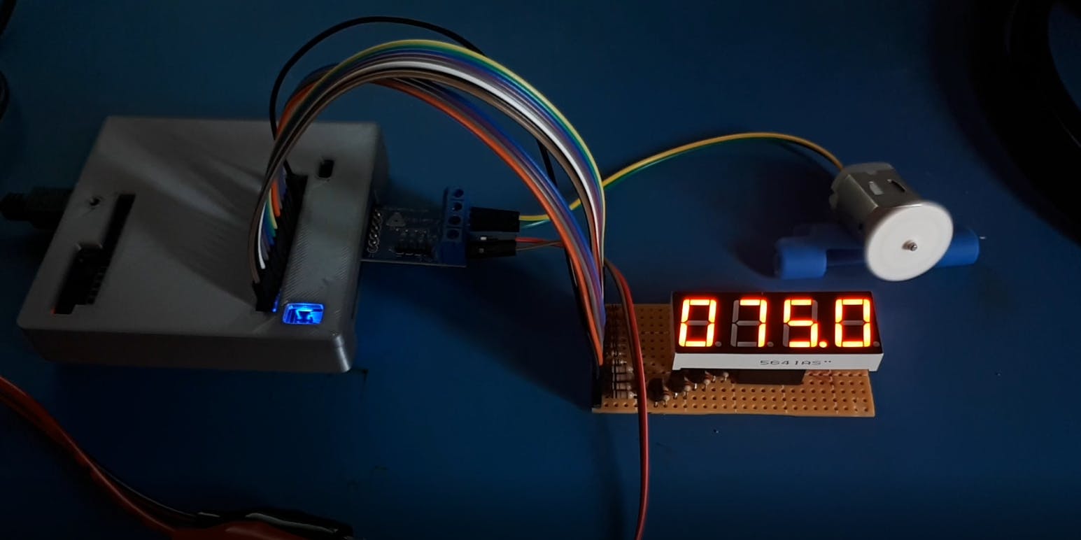
為了這個(gè)項(xiàng)目的需要,我為 5641AS 四位 7 段 LED 顯示器創(chuàng)建了一個(gè)手工制作的 PCB。段線通過300歐姆電阻連接到表頭,每個(gè)顯示器的共陰極由2N7000 N-MOS晶體管驅(qū)動(dòng),其柵極通過10k歐姆電阻連接到表頭并通過220k歐姆電阻接地。一個(gè) 13 針接頭(8 段、4 個(gè)公共陰極、1 個(gè) GND)通過 Arduino 連接器連接到 MiniZed。
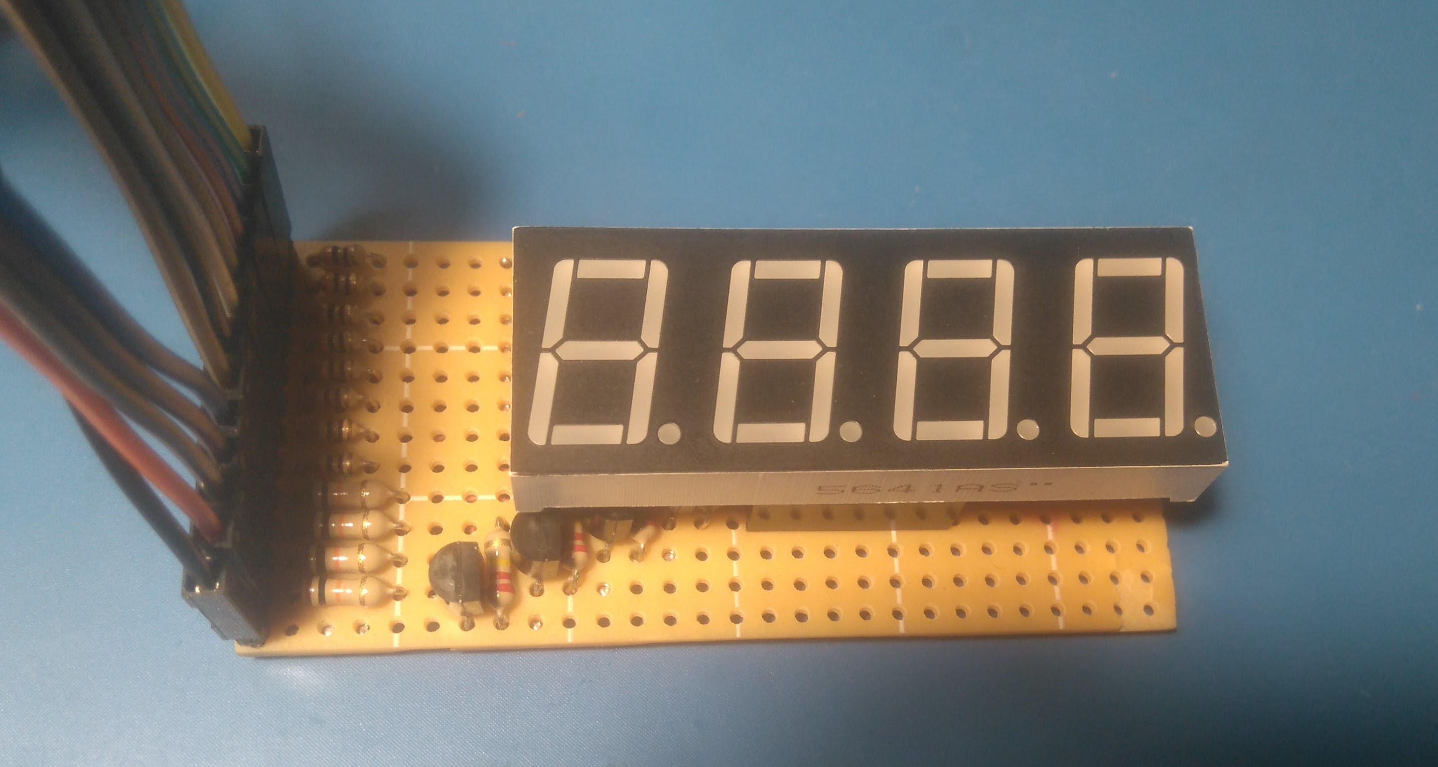
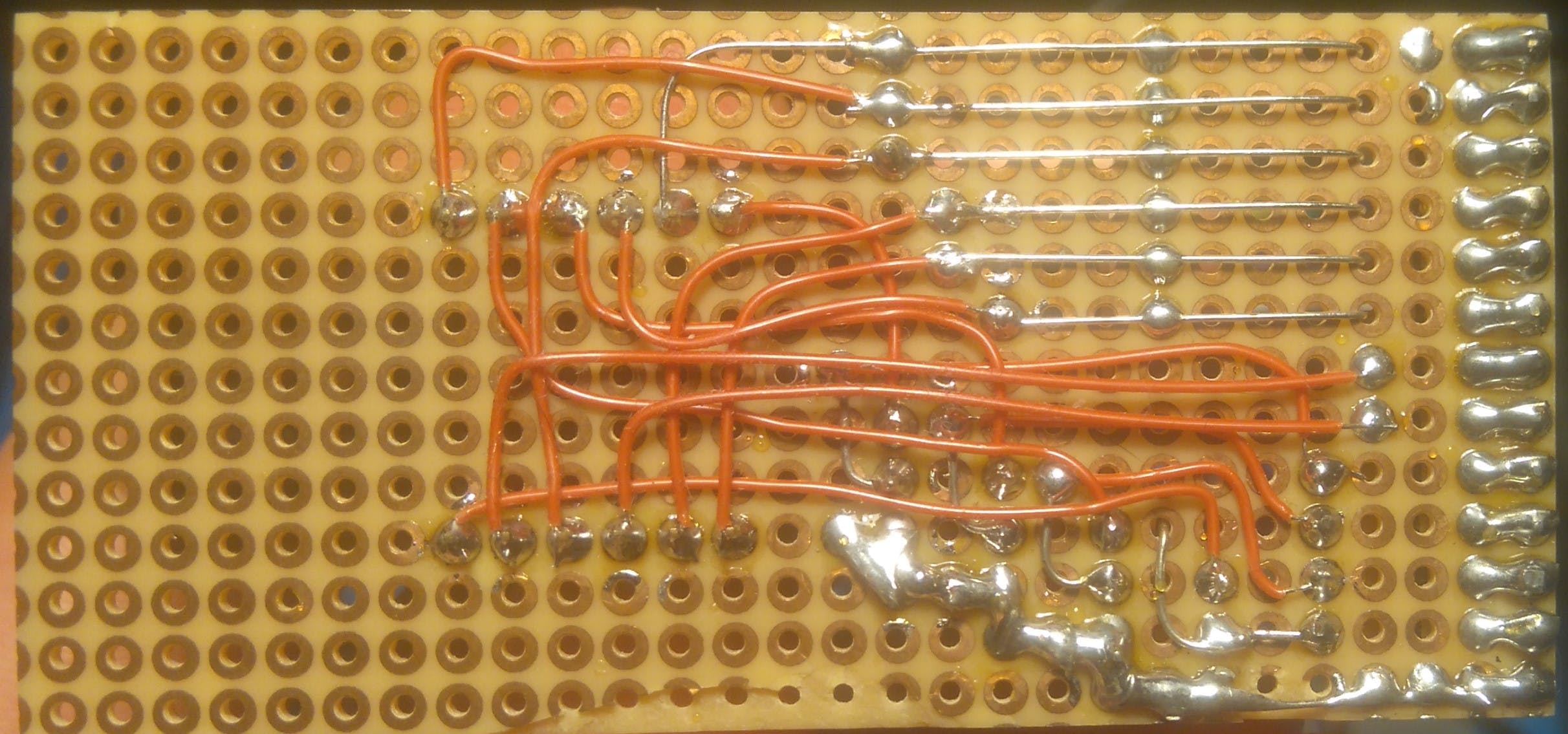
附板子原理圖和LED顯示屏內(nèi)部接線圖。但是,您可以使用其他具有類似硬件的顯示器和電路板。
創(chuàng)建 VHDL 7 段 LCD 顯示驅(qū)動(dòng)程序
我從框圖開始。輸入數(shù)據(jù)是一個(gè) 16 位數(shù)字,其中每 4 位是一個(gè)顯示器的編號(hào),因此最低有效 4 位是從右開始第一個(gè)顯示器的數(shù)字,連續(xù)的 4 位是下一個(gè)顯示器,最多 4 個(gè)最高有效位是從左數(shù)第 4 個(gè)顯示屏上的數(shù)字。因此 16 位二進(jìn)制數(shù) 0b0011001000010000 將顯示在顯示器 3210 上。第二個(gè) 4 位輸入用于顯示小數(shù)精度,其中最低有效位是從左數(shù)第一個(gè)顯示器上的點(diǎn),最高有效位是從左數(shù)第四個(gè)顯示器。所以 4 位二進(jìn)制數(shù) 0b0001 只會(huì)在左起第一個(gè)顯示器上顯示點(diǎn)。其他輸入是時(shí)鐘和復(fù)位,該模塊設(shè)計(jì)用于默認(rèn) 50 MHz 時(shí)鐘,并提供約 800Hz(每個(gè)數(shù)字 200 Hz)的顯示刷新率的結(jié)果。
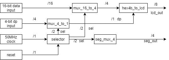
選擇器.vhd
該模塊分頻并控制多路復(fù)用器,2 位輸出地址 00 用于第一個(gè)顯示,11 用于最后一個(gè)顯示。
library IEEE;
use IEEE.STD_LOGIC_1164.ALL;
-- Uncomment the following library declaration if using
-- arithmetic functions with Signed or Unsigned values
use IEEE.NUMERIC_STD.ALL;
-- Uncomment the following library declaration if instantiating
-- any Xilinx leaf cells in this code.
--library UNISIM;
--use UNISIM.VComponents.all;
entity selector is
Port
(
clk, reset: in std_logic;
sel: out std_logic_vector(1 downto 0)
);
end selector;
architecture Behavioral of selector is
signal state, next_state: unsigned(17 downto 0);
begin
--register
process(clk, reset)
begin
if reset='1' then
state <= (others=>'0');
elsif (clk'event and clk='1') then
state <= next_state;
end if;
end process;
--next state logic
next_state <= state + 1;
--output clk/2^16 for 50MHz around 800 Hz out
sel <= std_logic_vector(state(17 downto 16));
end Behavioral;
mux_4_to_1.vhd
該模塊在當(dāng)前控制的 LED 顯示屏上設(shè)置點(diǎn)段。
library IEEE;
use IEEE.STD_LOGIC_1164.ALL;
-- Uncomment the following library declaration if using
-- arithmetic functions with Signed or Unsigned values
--use IEEE.NUMERIC_STD.ALL;
-- Uncomment the following library declaration if instantiating
-- any Xilinx leaf cells in this code.
--library UNISIM;
--use UNISIM.VComponents.all;
entity mux_4_to_1 is
Port
(
input  : in std_logic_vector (3 downto 0);
sw     : in std_logic_vector (1 downto 0);
output : out std_logic
);
end mux_4_to_1;
architecture Behavioral of mux_4_to_1 is
begin
with sw select
output <=
input(0)  when "00",
input(1)  when "01",
input(2)  when "10",
input(3)  when "11",
'0' when others;
end Behavioral;
mux_16_to_1.vhd
該模塊為當(dāng)前控制的 LED 顯示屏設(shè)置 16 位輸入的 4 位輸出。
library IEEE;
use IEEE.STD_LOGIC_1164.ALL;
-- Uncomment the following library declaration if using
-- arithmetic functions with Signed or Unsigned values
--use IEEE.NUMERIC_STD.ALL;
-- Uncomment the following library declaration if instantiating
-- any Xilinx leaf cells in this code.
--library UNISIM;
--use UNISIM.VComponents.all;
entity mux_16_to_4 is
Port
(
input  : in std_logic_vector (15 downto 0);
sw     : in std_logic_vector (1 downto 0);
output : out std_logic_vector (3 downto 0)
);
end mux_16_to_4;
architecture Behavioral of mux_16_to_4 is
begin
with sw select
output(3 downto 0) <=
input(3 downto 0)   when "00",
input(7 downto 4)   when "01",
input(11 downto 8)  when "10",
input(15 downto 12) when "11",
"0000" when others;
end Behavioral;
hex4b_to_lcd.vhd
將 4 位輸入數(shù)據(jù)轉(zhuǎn)換為當(dāng)前控制的 LED 顯示屏的輸出。
library IEEE;
use IEEE.STD_LOGIC_1164.ALL;
-- Uncomment the following library declaration if using
-- arithmetic functions with Signed or Unsigned values
--use IEEE.NUMERIC_STD.ALL;
-- Uncomment the following library declaration if instantiating
-- any Xilinx leaf cells in this code.
--library UNISIM;
--use UNISIM.VComponents.all;
entity hex4b_to_lcd is
Port
(
input:  in  std_logic_vector(3 downto 0);
dot:    in  std_logic;
output: out std_logic_vector(7 downto 0)
);
end hex4b_to_lcd;
architecture Behavioral of hex4b_to_lcd is
begin
with input select
output(6 downto 0) <=
"0111111" when "0000",
"0000110" when "0001",
"1011011" when "0010",
"1001111" when "0011",
"1100110" when "0100",
"1101101" when "0101",
"1111101" when "0110",
"0000111" when "0111",
"1111111" when "1000",
"1101111" when "1001",
"1110111" when "1010", --a
"1111100" when "1011", --b
"0111001" when "1100", --c
"1011110" when "1101", --d
"1111001" when "1110", --e
"1110001" when others; --f
output(7) <= dot;
end Behavioral;
seg_mux_4.vhd
模塊切換當(dāng)前使用的 LED 顯示。
library IEEE;
use IEEE.STD_LOGIC_1164.ALL;
-- Uncomment the following library declaration if using
-- arithmetic functions with Signed or Unsigned values
--use IEEE.NUMERIC_STD.ALL;
-- Uncomment the following library declaration if instantiating
-- any Xilinx leaf cells in this code.
--library UNISIM;
--use UNISIM.VComponents.all;
entity seg_mux_4 is
Port
(
input:  in  std_logic_vector (1 downto 0);
enable: in  std_logic;
output: out std_logic_vector (3 downto 0)
);
end seg_mux_4;
architecture Behavioral of seg_mux_4 is
begin
output <= "0000" when (enable = '0') else
"0001" when (input = "00") else
"0010" when (input = "01") else
"0100" when (input = "10") else
"1000" when (input = "11") else
"0000";
end Behavioral;
主.vhd
這是將上述所有模塊組合成 7 段顯示驅(qū)動(dòng)程序的頂層模塊。
library IEEE;
use IEEE.STD_LOGIC_1164.ALL;
-- Uncomment the following library declaration if using
-- arithmetic functions with Signed or Unsigned values
--use IEEE.NUMERIC_STD.ALL;
-- Uncomment the following library declaration if instantiating
-- any Xilinx leaf cells in this code.
--library UNISIM;
--use UNISIM.VComponents.all;
entity main is
Port
(
clk:       in std_logic;
dat_in:    in std_logic_vector(15 downto 0);
dp:        in std_logic_vector(3 downto 0);
reset    : in std_logic;
lcd_out:    out std_logic_vector (7 downto 0);
seg_out:    out std_logic_vector (3 downto 0)
);
end main;
architecture Behavioral of main is
signal num_sel: std_logic_vector (1 downto 0);
signal num_out: std_logic_vector (3 downto 0);
signal dp_out:  std_logic;
begin
u1: entity work.selector
port map(clk=>clk, reset=>reset, sel=>num_sel);
u2: entity work.mux_16_to_4
port map(input=>dat_in, sw=>num_sel, output=>num_out);
u3: entity work.seg_mux_4
port map(input=>num_sel, enable=>'1', output=>seg_out);
u4: entity work.mux_4_to_1
port map(input=>dp, sw=>num_sel, output=>dp_out);
u5: entity work.hex4b_to_lcd
port map(input=>num_out, dot=>dp_out, output=>lcd_out);
end Behavioral;
包含所有模塊的 VHDL 代碼文件以供使用和分析。
VHDL 模塊在 Mini But Mighty 項(xiàng)目中的實(shí)現(xiàn)
所以模塊是使用 VHDL 創(chuàng)建的,但是如何在 MiniZed 板上測(cè)試它呢?較大的 FPGA 板通常有 8 或 16 個(gè)輸入開關(guān)和 LED,用于測(cè)試在可編程邏輯中實(shí)現(xiàn)的硬件模塊的輸入和輸出。好的,我們?cè)?MiniZed 板上沒有足夠的 LED 和開關(guān),但我們有更多的東西,Zynq 7000 SoC,它有一個(gè) ARM Cortex - A9 處理器系統(tǒng) (PS) 和 Xilinx Artix 可編程邏輯 (PL)。我們可以使用和組合這些資源,在芯片內(nèi)部創(chuàng)建一個(gè)靈活的測(cè)試環(huán)境,并擁有我們需要的盡可能多的輸入和輸出。這將通過將創(chuàng)建的 VHDL 模塊實(shí)施到 Mini But Mighty 項(xiàng)目中來呈現(xiàn)。
起點(diǎn)將是Mini But Mighty項(xiàng)目。
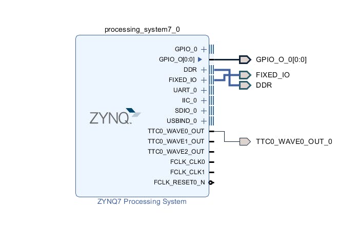
Vivado 硬件構(gòu)建
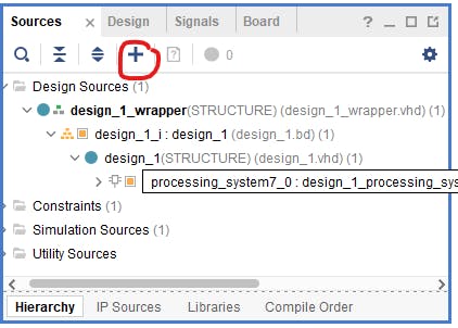
第一步是將我們創(chuàng)建的源添加到項(xiàng)目中。為此,我們使用選項(xiàng)卡源和“加號(hào)”按鈕。
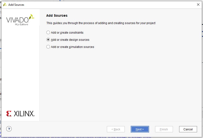
在下一步中,我們選擇“添加或創(chuàng)建設(shè)計(jì)源”。
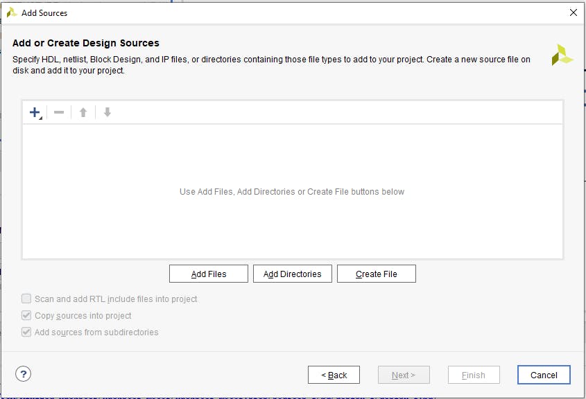
然后單擊“添加文件”按鈕。
我們選擇我們的 VHDL 文件并單擊“確定”。
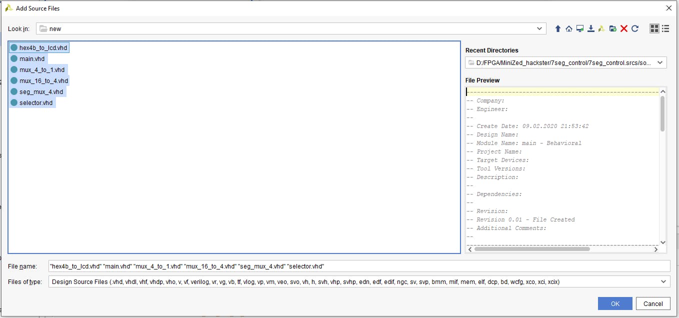
現(xiàn)在在添加源窗口中我們可以看到我們的 VHDL 文件。確保選中“將源代碼復(fù)制到項(xiàng)目中”,然后接受添加的源代碼并轉(zhuǎn)到下一步。
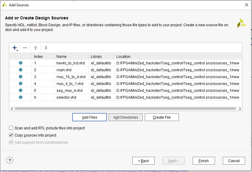
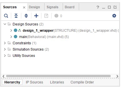
源窗口應(yīng)該是這樣的。
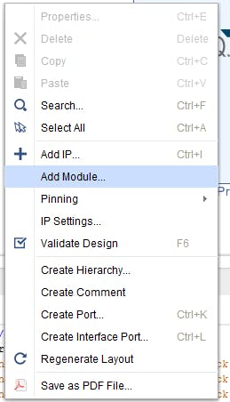
現(xiàn)在在塊空間的空白處單擊鼠標(biāo)右鍵并選擇“添加模塊”。
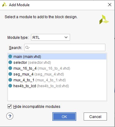
在新窗口中選擇“main.vhd”并單擊“確定”。
現(xiàn)在在塊設(shè)計(jì)中我們看到創(chuàng)建的 VHDL 模塊。
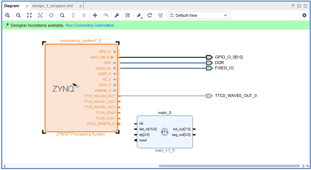
這個(gè)模塊是簡(jiǎn)單的 RTL 塊,我們需要一些 I/O 來使用它。我們將使用 axi_gpio IP,但首先我們需要配置處理系統(tǒng)。為此,雙擊 Zynq 塊并選擇 PS-PL 配置選項(xiàng)卡。
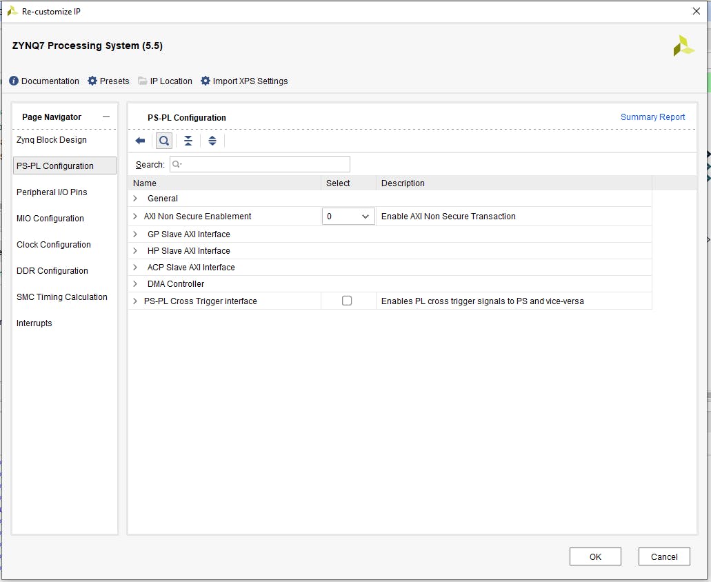
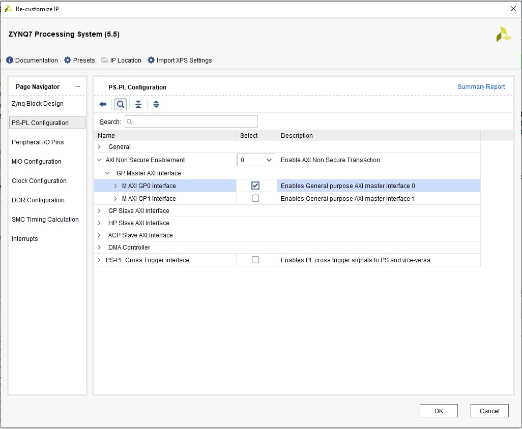
單擊“Axi Non Secure Enablement”,然后單擊“GP Master AXI Interface”并選擇“M AXI GP0 interface”并確認(rèn)更改。
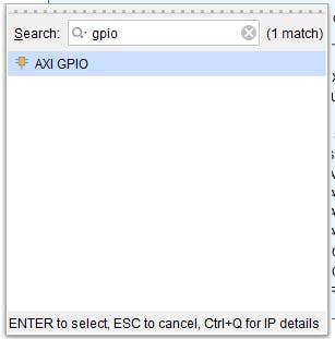
添加 AXI GPIO IP 是通過單擊塊設(shè)計(jì)中的“加號(hào)”按鈕,在搜索窗口中鍵入“gpio”并選擇“AXI GPIO”來完成的。
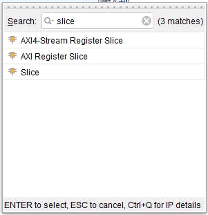
我們還需要兩個(gè)“切片”塊,因此重復(fù)最后一步兩次,在搜索框中鍵入“切片”。
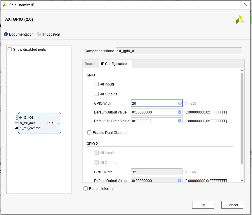
現(xiàn)在我們有了所有的元素,我們需要配置其中的一些。首先是 AXI GPIO,在 IP 設(shè)置配置選項(xiàng)卡中手動(dòng)設(shè)置 20 位寬度。
為 20 位輸入寬度和 15 到 0 輸出配置第一個(gè)切片,為 20 位輸入寬度和 19 到 16 輸出配置第二個(gè)切片。
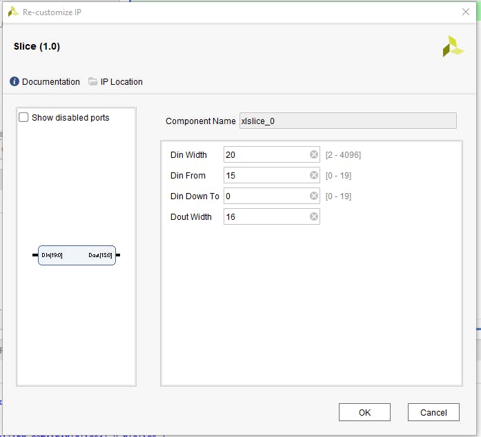
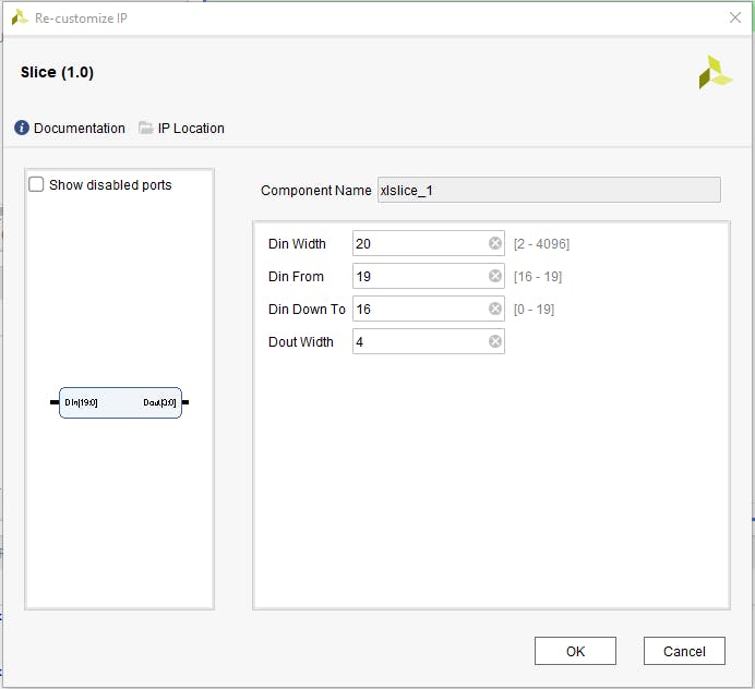
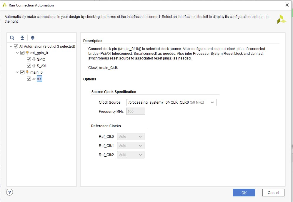
所有塊都已配置,因此應(yīng)建立它們之間的連接。為此,首先單擊“運(yùn)行連接自動(dòng)化”。

并選擇“All automation”(FCLK0 默認(rèn)配置為 50MHz,它是我們的 RTL 塊所需的輸入頻率)。
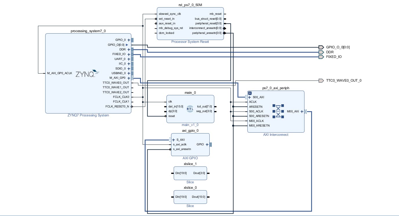
默認(rèn)情況下,Vivado 會(huì)將 VHDL 模塊復(fù)位連接到 peripheral_aresten,我們需要更正這一點(diǎn)并將復(fù)位連接到 peripheral_reset。
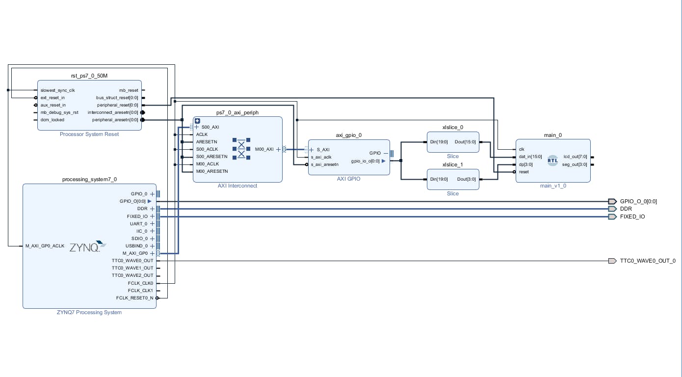
現(xiàn)在我們將切片塊連接到 axi_gpio_0 并將切片輸出連接到相應(yīng)的 RTL 模塊輸入。
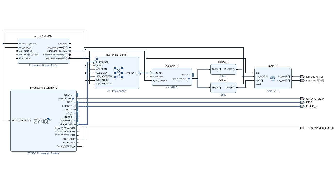
最后一步是使 RTL 模塊輸出到外部并保存塊設(shè)計(jì)。最終的塊設(shè)計(jì)如下。
在實(shí)施、合成和比特流生成之前,必須修改約束條件。顯示器的公共部分連接到 Arduino IO0 到 IO7,每個(gè)顯示器的公共陰極連接到 IO8 到 IO11。因此,我們必須在 io.xdc 文件中添加以下行。
set_property PACKAGE_PIN R8  [get_ports {lcd_out_0[7]}];  # "R8.ARDUINO_IO0"
set_property PACKAGE_PIN P8  [get_ports {lcd_out_0[6]}];  # "P8.ARDUINO_IO1"
set_property PACKAGE_PIN P9  [get_ports {lcd_out_0[5]}];  # "P9.ARDUINO_IO2"
set_property PACKAGE_PIN R7  [get_ports {lcd_out_0[4]}];  # "R7.ARDUINO_IO3"
set_property PACKAGE_PIN N7  [get_ports {lcd_out_0[3]}];  # "N7.ARDUINO_IO4"
set_property PACKAGE_PIN R10 [get_ports {lcd_out_0[2]}];  # "R10.ARDUINO_IO5"
set_property PACKAGE_PIN P10 [get_ports {lcd_out_0[1]}];  # "P10.ARDUINO_IO6"
set_property PACKAGE_PIN N8  [get_ports {lcd_out_0[0]}];  # "N8.ARDUINO_IO7"
set_property PACKAGE_PIN M9  [get_ports {seg_out_0[0]}];  # "M9.ARDUINO_IO8"
set_property PACKAGE_PIN N9  [get_ports {seg_out_0[1]}];  # "N9.ARDUINO_IO9"
set_property PACKAGE_PIN M10 [get_ports {seg_out_0[2]}];  # "M10.ARDUINO_IO10"
set_property PACKAGE_PIN M11 [get_ports {seg_out_0[3]}];  # "M11.ARDUINO_IO11"
set_property IOSTANDARD LVCMOS33 [get_ports -of_objects [get_iobanks 34]];
一旦創(chuàng)建了包裝器和約束,我們就可以實(shí)施設(shè)計(jì)了。選擇 Generate BitStream Option 并在設(shè)計(jì)編譯時(shí)等待幾分鐘。
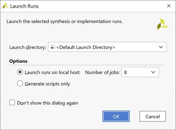
實(shí)施設(shè)計(jì)
一旦比特流可用,下一步就是導(dǎo)出 XSA 以在 Vitis 中使用。在文件下選擇導(dǎo)出-> 導(dǎo)出硬件。
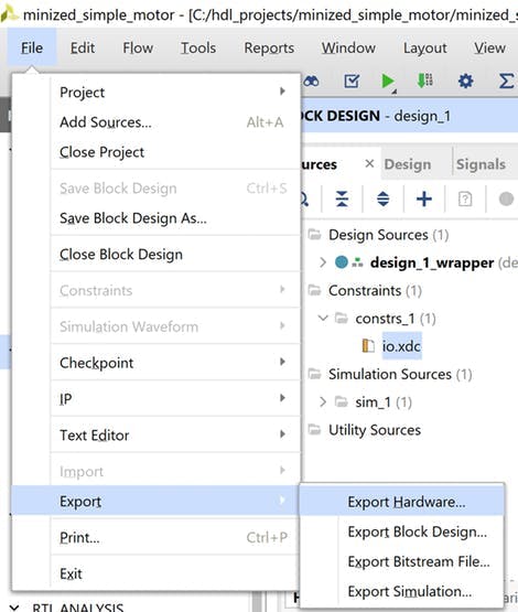
導(dǎo)出硬件
在出現(xiàn)的對(duì)話框中選擇包含比特流選項(xiàng)
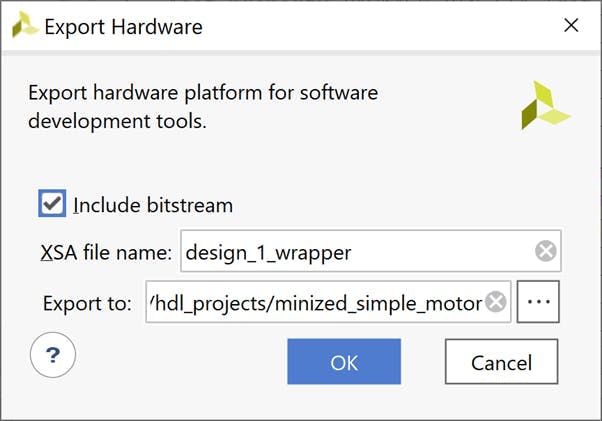
導(dǎo)出 XSA
我們現(xiàn)在準(zhǔn)備好打開 Vitis 并更新軟件應(yīng)用程序
Vitis 軟件構(gòu)建
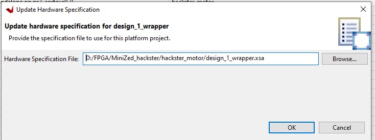
使用“工具”選項(xiàng)卡啟動(dòng) Vitis 并選擇 Mini But Mighty Workspace。現(xiàn)在我們必須更新硬件平臺(tái)。在 design_1_wrapper 上單擊鼠標(biāo)右鍵并選擇 Update Hardware Specification。
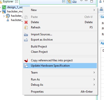
在新打開的窗口中,選擇更新的 XSA 文件并確認(rèn)。
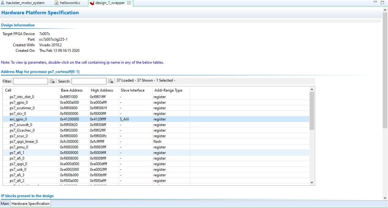
點(diǎn)擊build按鈕,等待編譯結(jié)束,然后打開platform.spr文件查看配置,axi_gpio_0應(yīng)該在Hardware Specification Address Map for processor list中。
現(xiàn)在我們將修改 helloworld.c 應(yīng)用程序以在我們的顯示器上顯示實(shí)際的 PWM。首先,我們需要為 AXI GPIO 添加額外的庫:
#include "xparameters.h"
#include "xgpio.h"
and定義:
#define GPIO_EXAMPLE_DEVICE_ID  XPAR_GPIO_0_DEVICE_ID
#define GPIO_CHANNEL 1
和 GPIO 驅(qū)動(dòng)程序?qū)嵗?/font>
XGpio GpioPL; /* The Instance of the GPIO Driver */
我們的 7 段 LED 顯示和硬件驅(qū)動(dòng)模塊默認(rèn)調(diào)整為十六進(jìn)制數(shù)。因此,我們需要?jiǎng)?chuàng)建一個(gè)函數(shù),以便在我們的軟件應(yīng)用程序中輕松使用十進(jìn)制數(shù):
uint8_t set_7seg_dec(uint16_t dec_num, uint8_t dp)
{
uint32_t seg7_out;
seg7_out = 0; // set 0 output
seg7_out = dp<<16; // set decimal point
seg7_out  |= (seg7_out & LED_MASK) | (dec_num % 10)*0x01;
seg7_out  |= (seg7_out & LED_MASK) | (dec_num / 10)%10*0x10;
seg7_out  |= (seg7_out & LED_MASK) | (dec_num / 100)%10*0x100;
seg7_out  |= (seg7_out & LED_MASK) | (dec_num / 1000)%10*0x1000;
XGpio_DiscreteWrite(&GpioPL, GPIO_CHANNEL, seg7_out);
return 0;
}
dec_num - 是 16 位無符號(hào)整數(shù),
dp - 是 8 位 usigned int 數(shù)字,其中 4 個(gè)最低有效位用于小數(shù)點(diǎn),例如 decimal 2 = 0b00000010 將在第二個(gè)顯示形式右側(cè)顯示點(diǎn)。
LED_MASK 是 0x0000FFFF 十六進(jìn)制數(shù),用于屏蔽 32 位 seg7_out 變量的小數(shù)點(diǎn)部分。
最后要做的是修改用于設(shè)置輸出 PWM 占空比的函數(shù)。我們通過將 set_7seg_function 添加到 set_pwm 函數(shù)并使用“cycle”變量來實(shí)現(xiàn)。變量乘以十是因?yàn)槲覀冊(cè)诘诙€(gè)顯示器上設(shè)置了小數(shù)點(diǎn):
void set_pwm(u32 cycle) {
u32 MatchValue;
set_7seg_dec(cycle*10, 2);
MatchValue = (TimerSetup->Interval * cycle) / 100;
XTtcPs_SetMatchValue(&ttcTimer, 0, MatchValue);
}
下面是修改后的 helloworld.c 的完整代碼,該文件也可以在 github 存儲(chǔ)庫中找到。
#include
之后我們必須保存文件并構(gòu)建項(xiàng)目。
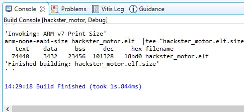
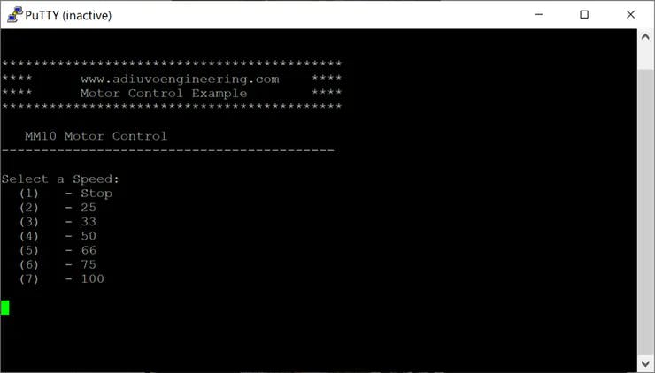
然后,如果沒有錯(cuò)誤,請(qǐng)單擊“運(yùn)行”按鈕并嘗試在終端中鍵入數(shù)字以更改 Pmod HB3 輸出上的脈沖寬度。實(shí)際占空比將顯示在 7 段 LED 顯示屏上。
包起來
該項(xiàng)目通過四路 7 段 LED 顯示示例和 Mini But Mighty 項(xiàng)目的更新展示了我們?nèi)绾问褂?AXI GPIO IP 將我們自己的 VHDL 或其他 HDL 模塊用于 Vivado 和 Vitis。可編程邏輯和處理系統(tǒng)的結(jié)合是強(qiáng)大的,唯一的限制是想象力。您可以對(duì)另一個(gè) HDL 模塊使用相同的方法。
- 帶7段顯示模塊MAX7219的秒表
- 7段LED時(shí)鐘開源分享
- 使用3x7段LED顯示器的反應(yīng)計(jì)時(shí)器 0次下載
- 使用WS2812b可單獨(dú)尋址LED制成的7段顯示器
- 一位7段LED顯示屏開源分享
- 4511 7位七段顯示模塊
- 離散4位LED7段顯示開源分享
- Arduino與Proteus仿真實(shí)例-7段數(shù)碼管(7線)驅(qū)動(dòng)仿真
- 如何在VHDL設(shè)計(jì)中使用庫模塊 13次下載
- 7段數(shù)碼管顯示的Proteus仿真電路圖和程序免費(fèi)下載 56次下載
- VHDL硬件描述語言入門教程資料免費(fèi)下載 43次下載
- 硬件描述語言VHDL 12次下載
- LED點(diǎn)陣顯示模塊驅(qū)動(dòng)設(shè)計(jì) 832次下載
- 使用MAX6954驅(qū)動(dòng)7段LED顯示器
- 7段數(shù)碼管譯碼器設(shè)計(jì)與實(shí)現(xiàn)
- 七段LED顯示器的工作原理與驅(qū)動(dòng)方法 979次閱讀
- LED數(shù)碼管顯示原理詳解 5418次閱讀
- 如何使用7段碼數(shù)碼管? 1633次閱讀
- 使用MAX6955 LED顯示驅(qū)動(dòng)器和PIC微控制器滾動(dòng)消息 814次閱讀
- 如何使用MAX7219和DS1307制作7段數(shù)字時(shí)鐘 3124次閱讀
- 基于7段LED的水位指示器電路圖 3345次閱讀
- 使用7段LED的比賽計(jì)分顯示電路圖介紹 3661次閱讀
- 基于鉆井深度顯示器和帶有Arduino支持的7段顯示器設(shè)計(jì) 2480次閱讀
- 微雪電子8段數(shù)碼管簡(jiǎn)介 1789次閱讀
- 基于一種模塊化的LED顯示屏設(shè)計(jì) 1848次閱讀
- 七段LED數(shù)碼管顯示原理 4w次閱讀
- Avnet MiniZed單核Zynq 7Z007S入門開發(fā)方案 5161次閱讀
- 7段數(shù)碼管顯示的VHDL設(shè)計(jì)(兩款設(shè)計(jì)方案) 2.1w次閱讀
- 開關(guān)控制數(shù)碼管的VHDL程序的設(shè)計(jì)與實(shí)現(xiàn) 5186次閱讀
- LED顯示系統(tǒng)DMA控制器的設(shè)計(jì) 3137次閱讀
下載排行
本周
- 1使用單片機(jī)實(shí)現(xiàn)七人表決器的程序和仿真資料免費(fèi)下載
- 2.96 MB | 44次下載 | 免費(fèi)
- 2Keysight B1500A 半導(dǎo)體器件分析儀用戶手冊(cè)、說明書 (中文)
- 19.00 MB | 4次下載 | 免費(fèi)
- 3BT134雙向可控硅手冊(cè)
- 1.74 MB | 2次下載 | 1 積分
- 4一種新型高效率的服務(wù)器電源系統(tǒng)
- 0.85 MB | 1次下載 | 1 積分
- 5臺(tái)達(dá)VFD-M系列變頻器驅(qū)動(dòng)板原廠原理圖
- 0.17 MB | 1次下載 | 免費(fèi)
- 6WTS-100(1.1) UWB 信標(biāo)定位系統(tǒng) 彩頁
- 540.48 KB | 1次下載 | 免費(fèi)
- 7雙向DC-DC轉(zhuǎn)換器用戶指南
- 2.98MB | 1次下載 | 免費(fèi)
- 8聯(lián)想E46L DAOLL6筆記本電腦圖紙
- 1.10 MB | 1次下載 | 5 積分
本月
- 1使用單片機(jī)實(shí)現(xiàn)七人表決器的程序和仿真資料免費(fèi)下載
- 2.96 MB | 44次下載 | 免費(fèi)
- 2UC3842/3/4/5電源管理芯片中文手冊(cè)
- 1.75 MB | 15次下載 | 免費(fèi)
- 3DMT0660數(shù)字萬用表產(chǎn)品說明書
- 0.70 MB | 13次下載 | 免費(fèi)
- 4ST7789V2單芯片控制器/驅(qū)動(dòng)器英文手冊(cè)
- 3.07 MB | 11次下載 | 1 積分
- 5TPS54202H降壓轉(zhuǎn)換器評(píng)估模塊用戶指南
- 1.02MB | 8次下載 | 免費(fèi)
- 6STM32F101x8/STM32F101xB手冊(cè)
- 1.69 MB | 8次下載 | 1 積分
- 7TPS92682-Q1幀定義和示例
- 891.71KB | 6次下載 | 免費(fèi)
- 8HY12P65/HY12P66數(shù)字萬用表芯片規(guī)格書
- 0.69 MB | 6次下載 | 免費(fèi)
總榜
- 1matlab軟件下載入口
- 未知 | 935119次下載 | 10 積分
- 2開源硬件-PMP21529.1-4 開關(guān)降壓/升壓雙向直流/直流轉(zhuǎn)換器 PCB layout 設(shè)計(jì)
- 1.48MB | 420061次下載 | 10 積分
- 3Altium DXP2002下載入口
- 未知 | 233084次下載 | 10 積分
- 4電路仿真軟件multisim 10.0免費(fèi)下載
- 340992 | 191367次下載 | 10 積分
- 5十天學(xué)會(huì)AVR單片機(jī)與C語言視頻教程 下載
- 158M | 183335次下載 | 10 積分
- 6labview8.5下載
- 未知 | 81581次下載 | 10 積分
- 7Keil工具M(jìn)DK-Arm免費(fèi)下載
- 0.02 MB | 73807次下載 | 10 積分
- 8LabVIEW 8.6下載
- 未知 | 65987次下載 | 10 積分
 電子發(fā)燒友App


 創(chuàng)作
 發(fā)文章
 發(fā)帖
  提問
提問  發(fā)資料
 發(fā)視頻
 上傳資料賺積分


評(píng)論