Abstract: MAX9485 is a versatile, programmable, audio clock generator. It consists of a VCXO, fractional-N PLL, and I2C interface. To use the MAX9485 appropriately, it is important that the power level of the VCXO's crystal does not exceed its maximum rating. This application note describes a simple method for measuring the power level of a crystal oscillator, and reports the test results on the MAX9485.
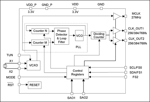
Figure 1. Functional diagram of the MAX9485 clock generator.
When using the MAX9485, the crystal's power level should be less than the maximum rating given by the crystal's manufacturer. If the crystal's driving level is higher than its maximum rating, the crystal's equivalent serial resistance (ESR) and frequency accuracy may degrade. If the crystal's power were 10x over its maximum rating, it could cause irreversible damage to the crystal.
In this application note, we first review the formula for calculating a crystal's power level. We then introduce a simple test setup for measuring the crystal's power level, and finally present the test result from the MAX9485.
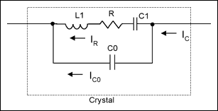
Figure 2. Circuit diagram of a crystal Equivalent.
The ESR R, shown in Figure 2, of a crystal causes the crystal to consume power. If the RMS (root of mean square) current going through R is IR, then we can obtain the crystal's power level by;

However, in practice, IR is not measurable. When a crystal is resonating, the impedance of the LC branch is much smaller than that of the C0 branch. Therefore, we can use IC to approximate IR. Thus, we get a practical formula for the crystal's power-level calculation:

The current going through the crystal is AC and its waveform is often sinusoidal or saw-tooth. The following relations determine the RMS values of sine-wave and saw-tooth wave currents from their peak-to-peak amplitudes.

where IPP is the peak-to-peak value of the current.
Measuring the crystal's current is not straightforward. In the test setup shown in Figure 3, we use a small 10Ω resistor to sense the current. We know that using the 10Ω resistor is valid, because changing the resistor to 20Ω barely changed the sensed current.
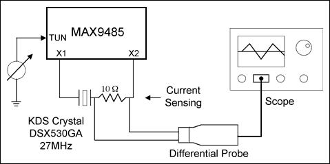
Figure 3. Setup for testing a crystal's power level.
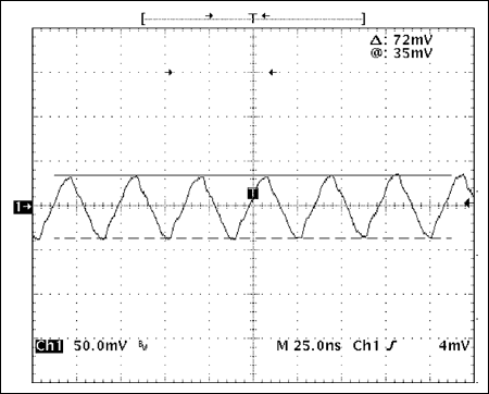
Figure 4. Voltage waveform across the 10Ω resistor at 26.99500MHz (-185PPM).
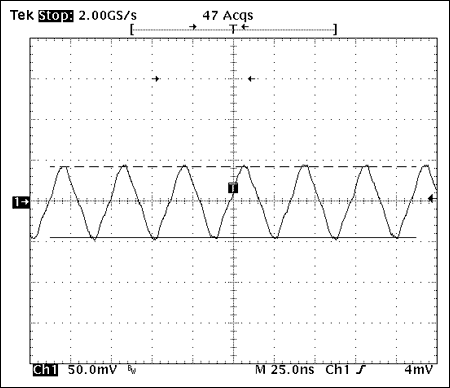
Figure 5. Voltage waveform across the 10Ω resistor at 27.00000MHz (0PPM).
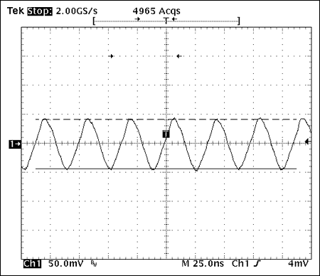
Figure 6. Voltage waveform across the 10Ω resistor at 27.00400MHz (148PPM).
In calculating the crystal's power level, we consider two scenarios: (1) the worst case (that is, the maximum R value), and (2) the typical case.
The R value shown in the DSX530GA data sheet is 50Ω. This is, however, the absolute maximum for the 12MHz to 54MHz frequency range. Typically, the higher the crystal frequency, the less the R value. We consulted with KDS America and were informed that for a 27MHz DSX530GA crystal, the maximum R value (case #1) is less than 40Ω, and the typical value (case #2) is 20Ω. As shown in the plots above, the crystal currents have saw-tooth waveforms. We thus use Equation 4 to calculate the crystal RMS current from its peak-to-peak value. Therefore, the crystal's calculated power levels are shown in Table 1.
Table 1. Measured Results and Crystal Power Levels
Note: (1) The RMS value of a saw-tooth waveform is 1/2 of the peak-to-peak value.
[1] MAX9485 data sheet
[2] MAX9485 application note 2097, "Using a VCXO (Voltage-Controlled Crystal Oscillator) as a Clock (CLK) Generator."
[3] See the application note 2127, "Modeling of Quartz Crystal."
[4] DSX530GA data sheet
|
|
Introduction
The MAX9485[1, 2] is a cost-effective, programmable, multiple-output audio clock generator for MPEG-2 or AC-3 audio systems such as DVD players, a DVD drive for multimedia PC's, HDTV's, home entertainment centers, and set-top boxes. The MAX9485 has a fractional-N programmable PLL with two output drivers, a VCXO with ±200 PPM pulling range, and an I2C interface. Its system functional diagram is shown in Figure 1.
Figure 1. Functional diagram of the MAX9485 clock generator.
When using the MAX9485, the crystal's power level should be less than the maximum rating given by the crystal's manufacturer. If the crystal's driving level is higher than its maximum rating, the crystal's equivalent serial resistance (ESR) and frequency accuracy may degrade. If the crystal's power were 10x over its maximum rating, it could cause irreversible damage to the crystal.
In this application note, we first review the formula for calculating a crystal's power level. We then introduce a simple test setup for measuring the crystal's power level, and finally present the test result from the MAX9485.
Calculation of a Crystal's Power Level
Figure 2 illustrates a circuit that functions equivalent to a crystal[3].
Figure 2. Circuit diagram of a crystal Equivalent.
The ESR R, shown in Figure 2, of a crystal causes the crystal to consume power. If the RMS (root of mean square) current going through R is IR, then we can obtain the crystal's power level by;

However, in practice, IR is not measurable. When a crystal is resonating, the impedance of the LC branch is much smaller than that of the C0 branch. Therefore, we can use IC to approximate IR. Thus, we get a practical formula for the crystal's power-level calculation:

The current going through the crystal is AC and its waveform is often sinusoidal or saw-tooth. The following relations determine the RMS values of sine-wave and saw-tooth wave currents from their peak-to-peak amplitudes.

where IPP is the peak-to-peak value of the current.
Crystal Power-Level Test Setup
For the MAX9485, we recommend that you use the 27MHz crystal (DSX530GA)[4] from KDS America. This crystal has a rated maximum power level of 300μW.Measuring the crystal's current is not straightforward. In the test setup shown in Figure 3, we use a small 10Ω resistor to sense the current. We know that using the 10Ω resistor is valid, because changing the resistor to 20Ω barely changed the sensed current.

Figure 3. Setup for testing a crystal's power level.
Measurement Data and Power-Level Calculation
Using the test setup in Figure 3, the highest crystal power level occurs at 27MHz, which is around the center of the VCXO tuning range. The following plots (Figures 4, 5, and 6) are the measured voltage waveforms across the current-sensing resistor at different frequencies. To reduce the measurement noise, the scope's 250MHz lowpass filter is turned on.
Figure 4. Voltage waveform across the 10Ω resistor at 26.99500MHz (-185PPM).

Figure 5. Voltage waveform across the 10Ω resistor at 27.00000MHz (0PPM).

Figure 6. Voltage waveform across the 10Ω resistor at 27.00400MHz (148PPM).
In calculating the crystal's power level, we consider two scenarios: (1) the worst case (that is, the maximum R value), and (2) the typical case.
The R value shown in the DSX530GA data sheet is 50Ω. This is, however, the absolute maximum for the 12MHz to 54MHz frequency range. Typically, the higher the crystal frequency, the less the R value. We consulted with KDS America and were informed that for a 27MHz DSX530GA crystal, the maximum R value (case #1) is less than 40Ω, and the typical value (case #2) is 20Ω. As shown in the plots above, the crystal currents have saw-tooth waveforms. We thus use Equation 4 to calculate the crystal RMS current from its peak-to-peak value. Therefore, the crystal's calculated power levels are shown in Table 1.
Table 1. Measured Results and Crystal Power Levels
| Frequency MHz/PPM |
Peak-to-Peak Voltage on 10Ω (mV) |
Peak-to-Peak Current (mA) |
RMS(1) Current (IC) |
Max Power (mΩ) IC2 x R R = 40Ω |
Typ Power (mΩ) IC2 x R R = 20Ω |
| 26.995/-185 | 72 | 7.2 | 3.6/ |
172.8 | 86.4 |
| 27.000 0 | 88 | 8.8 | 4.4/ |
258.13 | 129 |
| 27.004/148 | 86 | 8.6 | 4.3/ |
246.5 | 123.2 |
Note: (1) The RMS value of a saw-tooth waveform is 1/2
 of the peak-to-peak value.
Conclusions
We can make some observations from Table 1.- In the worst case, the crystal power level of the MAX9485 is about 40μW less than the maximum power level (300μW) of DSX530GA.
- In the typical case, with the realistic value of R at 27MHz, the power level is well under the maximum power level (300μW).
- For the VCXO in the MAX9485, the highest crystal current occurs at the middle of the tuning range and the power variation is relatively small within the tuning range.
[1] MAX9485 data sheet
[2] MAX9485 application note 2097, "Using a VCXO (Voltage-Controlled Crystal Oscillator) as a Clock (CLK) Generator."
[3] See the application note 2127, "Modeling of Quartz Crystal."
[4] DSX530GA data sheet
 電子發燒友App






評論