The use of data cables for connecting cell phones and other mobile appliances will become more prevalent as the demand for mobile communications increases. New, faster-data-rate cell-phone standards such as GPRS, WCDMA, and UMTS will need data cables to achieve the higher levels of functionality and Internet connectivity inherent in next-generation smart phones, and these data cables pose unusual problems for the designers of mobile phone accessories.
Some cables carry only TTL signals, but the most common interface standard for today's data cables is RS-232. Also emerging is a need for USB-level translators. This article concentrates on the RS-232 standard, but many of the design issues discussed can be applied to both TTL and USB cables.
For mobile phones and other low-cost consumer devices, it makes little economic sense to add data capability costing a couple of dollars or so to everyone's base unit when only 5% to 10% of all users have a need for this capability. The first order of business, therefore, is to decide which type of level translator meets a given system requirement, that is, what sort of communications must be supported.
Full Modem Specification
In many applications the phone should appear to the PC as a modem, because commercial software for e-mail or web surfing is then readily available. Five drivers and three receivers are needed to implement a full-modem DCE interface. The MAX3248E RS-232 transceiver implements this requirement, as do similar components from other manufacturers.A simplified diagram of a data cable (Figure 1) shows that both connectors can be exposed to ESD strikes, so it needs extra components for ESD protection, both on the logic side and the RS-232 side. To accommodate the low voltages of cell-phone ASICs, it may also need to include a level-translation capability. A full-modem interface can be excessive, however. It requires 10 connector pins on the bottom of the phone, which makes it an expensive option.

Figure 1. An IC and its associated components form a lump (data lump) in this PC-to-phone cable.
As a cheaper alternative, you can implement a hardware hand-shaking link that level-translates only the signals RX, TX, CTS, and RTS in the cell-phone data cable. This approach requires that you (or someone) write driving software for the PC side: either the specialized phone-sync software for updating address books, or a software bridge that converts all eight standard RS-232 signals to a 2/2 format. For custom cables, this approach can be acceptable and much cheaper. For the other combinations of transmitters and receivers that can be required for specific applications, Maxim offers a wide selection of RS-232 devices.
VCC Considerations
Most data-lump cables (so-called because the presence of ICs and other components produce a visible lump in the cable) derive power from the portable appliance. Some older portable appliances operate on four NiMh or NiCad cells, but the most common battery technology today is a single-cell Li-ion battery. The cell measures about 4.2V when fully charged and about 2.4V when fully discharged.A phone with exposed connectors, carried in a pocket, runs the risk that a loose coin can short out its battery. To prevent this kind of accident, the phone limits battery current with either a current-limited linear regulator or a Polyswitch? (a type of resettable fuse that opens under high current and re-closes when the current returns to normal). The battery voltage in question can be anywhere in the range 2.4V to 4.2V.
The RS-232 specification requires that RS-232 transmitters be capable of maintaining ±5.0V across a 3kΩ load. The majority of transmitters, however, guarantee this output level for supply voltages no lower than 3.0V. An internal charge-pump doubler whose high output resistance imposes a need for "dropout voltage" drives the transmitter output. As a result, the chip cannot maintain ±5.0V across 3kΩ for inputs less than 3V.
On the other hand, RS-232 receiver thresholds are only 2.4V high and 0.6V low. A 2.6V difference is specified (5.0V supply minus 2.4V receiver threshold), because RS-232 was intended originally as a long-distance standard capable of driving 100 feet or more of cable, whereas data-cable applications seldom transmit more than 5 or 6 feet. Thus, the question is whether the data lump should be RS-232 compliant (meets every letter of the specification) or RS-232 compatible (simply works in a data-cable environment).
RS-232 Compatible or Compliant?
To meet the RS-232 spec for ±5.0V transmit voltages, transceivers like the MAX3227E, the MAX3238E, and the MAX3386E guarantee operation only for supply voltages between 3.0V and 5.5V. The charge pumps, however, function at voltages much lower than this and typically start as low as 2.0V. This condition lowers the transmitter voltage slightly, but places ±4V on the line meeting the 2.4V receiver threshold. To illustrate, Figure 2 shows the MAX3232's output level for a 9600-baud signal driving into a receiver with input resistance between 3kΩ and 7kΩ. Power is supplied via a 1-meter "category 5" cable.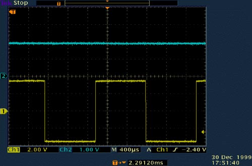
Figure 2. With a 2V input (top trace), this MAX3232 output (bottom trace) drives almost ±4V into an RS-232 receiver input.
If true RS-232 levels are required with the supply voltage less than +3.0V, then an RS-232 transceiver such as the MAX3212 or the MAX3218, based on a boost architecture, offers the most economical solution. As shown in Figure 3, these transceivers operate with an external diode, a capacitor, and a small and inexpensive surface-mount chip inductor. This family of devices generates RS-232-compliant levels with input voltages as low as 1.8V.

Figure 3. This RS-232 transceiver's internal boost controller ensures true RS-232 levels, even with supply voltages less than 3.0V.
Increased Current Draw
As input voltage to the RS-232 transceivers decreases, the transceiver tries to maintain a ±5V output across the receiver load, causing an increase in current draw from the battery. If you don't provide local decoupling in a data-cable application, this current flow via the cable's distributed inductance and resistance causes local ringing in VCC. A scope plot (Figure 4) shows the current waveform produced by powering the MAX3232 via this cable without proper decoupling. The result is a fair amount of ringing, with current spikes up to 80mA. In this case, the scale is 20mA/Div, VIN at the remote end of the cable equals 3.0V, and the part without decoupling fails to start.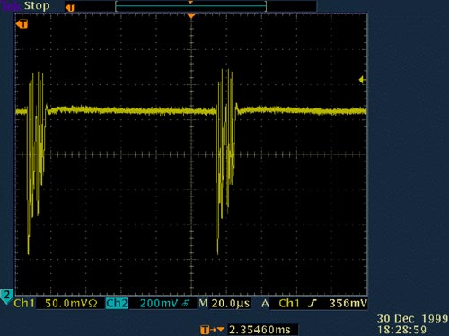
Figure 4. Transceiver power flowing through the cable inductance causes ringing, unless you provide adequate decoupling.
Ringing can produce unwanted emissions. To minimize this effect, provide good localized decoupling and a short cable length to the data lump. Because ground must be provided with the signals anyway, you should consider a shielded cable. Figure 5 shows the improvement made by adding 4.7μF and 0.1μF capacitors in parallel between VCC and ground in the data lump.
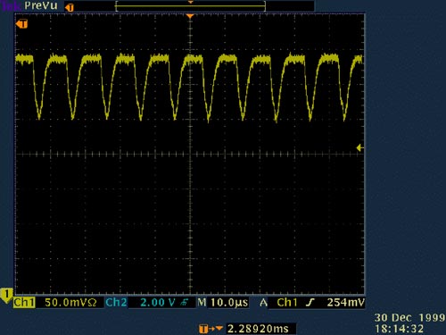
Figure 5. Decoupling capacitors tame the ringing in Figure 4.
Logic Compatibility
The reduction in core supply voltages for cell phones (to 2.5V and potentially to 1.8V) can cause a logic-compatibility problem between the cell phone and the data lump. (When optimized for 3V logic, typical RS-232 transceivers have VIH levels of 2.0V.) This problem is usually solved with discrete logic-level translators within either the phone or the data lump. As a simpler alternative, you can employ the MAX3386E or MAX3238E transceiver. With external voltage applied to the MAX3386E VL pin, its internal threshold levels assume 1/3 and 2/3 (VIL and VIH) of that voltage. The MAX3238E offers various trip thresholds compatible with 2.5V logic and the future 1.8V logic.Saving Power
Battery life is of primary concern in these battery-powered systems. In addition to their nominal 1mA quiescent current, RS-232 transceivers draw power for each transmitter. The static draw is typically 5.5V into a 5kΩ load, or 1.1mA. When reflected back to the input supply, this current approximately doubles (assuming VIN > 3V and a perfect charge pump). Even worse, a full modem interface can draw a nominal current greater than 12mA before transmitting any data.When no data is being transmitted, the transceiver should be shut down to save battery power. One technique is to run an extra line from the phone for that purpose, but an extra pin on the phone connector adds expense. An alternative is the AutoShutdown Plus? transceiver.
AutoShutdown Plus monitors the transmitter inputs and receiver inputs for valid edge activity. If the IC senses no change of state at any input for 30 seconds, it switches the internal charge pump and drivers off, reducing the supply current to only 1μA. Then, any transition on the TTL side or the RS-232 side causes the device to power up and return to a normal operating mode.
ESD Protection
Data cables can be zapped with electrostatic discharge (ESD) on either the TTL or RS-232 side of the data lump. To be sold within the EEC, a data cable must withstand rated levels of ESD as defined in three tests. Device inputs and outputs need extra protection to meet the following stringent requirements:| ±15kV | Human Body Model |
| ±8kV | IEC 1000-4-2, Contact Discharge Method |
| ±15kV | IEC 1000-4-2, Air Gap Discharge |
ESD protection can be added externally, using TranZorbs?, spark gaps, or combinations of resistors, capacitors, and inductors. These methods can be costly, because all inputs and outputs must be protected (16 lines for a full modem interface). Many manufacturers now offer internal ESD protection on the RS-232 side (see the list below), which helps to cut down on space and cost. Newer devices such as the MAX3238E include ESD protection on the TTL side as well.
RS-232 Line Driver/Receivers:
| MAX221E | MAX3241E |
| MAX3221E | MAX3243E |
| MAX3222E | MAX3244E |
| MAX3223E | MAX3245E |
| MAX3224E | MAX3248E |
| MAX3225E | MAX3314E |
| MAX3226E | MAX3316E |
| MAX3227E | MAX3317E |
| MAX3233E | MAX3318E |
| MAX3235E | MAX3319E |
| MAX3237E | MAX3386E |
| MAX3238E | MAX3387E |
Onboard ESD structures work by shorting ESD strikes to ground, and the device should return to normal operation after the strike. Following an ESD event, some devices require that the supply voltage be cycled on/off/on to remove latchups and restore normal operation (Maxim devices don't require this power cycling). Because the fault current goes to ground, the ground connection should be kept short to reduce the effects of ground bounce. And, because the ground return is on the logic side of the lump, it makes sense to keep that length of cable as short as possible. Good localized decoupling within the data lump acts as a local power source during ESD strikes.
Hot Synchronizing
Handheld PDAs have brought about a new feature in data cables: the ability to synchronize a device to the PC using a cradle (for example, Palm's? Hotsync?). To tell the PC software when the device is connected, the device generates an interrupt via the RS-232 connector's ring-indicate signal. This method is less software intensive than continual polling of the RS-232 port, but it requires an extra transmitter output.A similar version of this article appeared in the December 2000 issue of Portable Design.
HotSync is a registered trademark of PalmSource Inc.
Palm is a registered trademark of Palm, Inc.
TransZorb is a registered trademark of Vishay Intertechnology, Inc.
 電子發燒友App






評論