Before OTG, the concept of an embedded host was already established in the USB world. Instead of duplicating the full UHCI/OHCI USB controllers and drivers built into personal computers, most embedded host chips provide limited hosting capabilities. This makes them better suited to the embedded environment than to the PC with its huge resources and infinite capacity for drivers and application software.
Introduction
USB On-The-Go (OTG) allows two USB devices to talk to each other without requiring the services of a personal computer (PC). Although OTG appears to add peer-to-peer connections to the USB world, it does not. Instead, USB OTG retains the standard USB host/peripheral model, in which a single host talks to USB peripherals. OTG does introduce, however, the dual-role device, or simply stated, a device capable of functioning as either host or peripheral. Part of the magic of OTG is that a host and peripheral can exchange roles if necessary.Before OTG, the concept of an embedded host was already established in the USB world. Instead of duplicating the full UHCI/OHCI USB controllers and drivers built into PCs, most embedded host chips provide limited hosting capabilities. This makes them better suited to the embedded environment than a PC with its huge resources and infinite capacity for drivers and application software.
An OTG device may, or may not be capable of functioning as a host. It is likely, nonetheless, that most OTG devices will be dual-role.
USB Peripherals
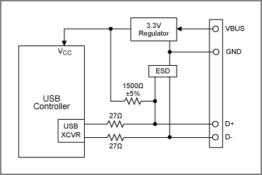
Figure 1 illustrates the basic USB peripheral circuitry on which OTG builds. These example peripherals operate at low or full speed, and are commonly known as USB 1.1 devices. This nomenclature is used even though the USB 2.0 Specification includes the current USB 1.1 specification and introduces a third, higher speed.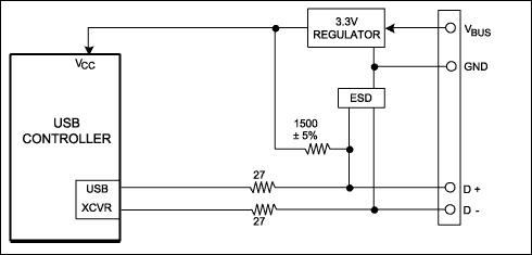
Figure 1. A USB peripheral controller and its associated circuitry.
The controller in Figure 1 might be a microprocessor plus USB SIE (Serial Interface Engine), an integrated microprocessor/USB chip, or an ASIC connected to a USB transceiver. A bus-powered peripheral requires a 3.3V regulator, both to power the logic and to supply the proper voltage to a 1500Ω resistor connected to either the D+ or D- USB pins. This pullup resistor signals the host that a device is connected, and indicates the device's operating speed. A pullup to D+ indicates full speed; a pullup to D- indicates low speed. The other end of the connection—host or hub—contains 15kΩ pulldown resistors on D+ and D- so the pullup resistor can be detected. Finally, an ESD protection circuit is advisable on D+, D-, and VBUS pins because USB is designed to be hot-plugged.
How to Be a Host
The Figure 1 circuit functions only as a USB peripheral device. To add OTG dual-role capability, the transceiver must be augmented to allow the OTG device to function as either host or peripheral. Adding the following to Figure 1 lets the system also function as a host:- 15kΩ pulldown resistors on D+ and D-
- A means to supply, rather than draw, power on VBUS
- Send SOF (Start of Frame) packets.
- Send SETUP, IN, and OUT packets.
- Schedule transfers within USB 1ms frames.
- Signal USB reset.
- Provide USB power management.
Host Negotiation Protocol
An OTG dual-role device can operate either as a host or peripheral. In OTG nomenclature, the initial host is called the A-Device, and the initial peripheral is called the B-Device. The word initial is important. Once connected, OTG dual-role devices can exchange roles—host and peripheral—by using the new Host Negotiation Protocol (HNP). HNP raises two obvious questions: (a) how are the initial roles determined; and (b) why is the role reversal necessary?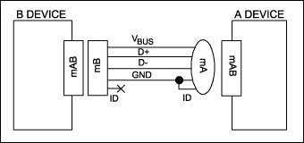
Figure 2. Fifth ID pin determines default host.
The cable orientation determines the initial roles (Figure 2). Dual-role devices use a new receptacle called the mini-AB. The mini-A plug, the mini-B plug and the mini-AB receptacle add a fifth pin (ID) to give different electrical identities to the cable ends. This fifth ID pin is connected to ground inside the mini-A plug and left floating in the mini-B plug. The OTG device receiving the grounded ID pin is the default A-Device (host); the device with the floating ID pin is the default B-Device (peripheral).
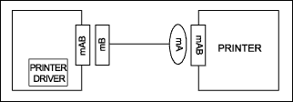
Figure 3. OTG cable is inserted backwards.
To understand the need for the HNP and host/peripheral role reversal, the example in Figure 3 shows two dual-role devices, a PDA and a printer. The PDA has a printer driver inside. The two devices are connected with the new OTG cable as shown, making the printer the default host (A-Device) and the PDA the default peripheral (B-Device). But this setup is backwards. The PDA, which has the printer driver, needs to act as USB host to the printer, which contains no driver. Rather than bothering the user to reverse the cable, HNP allows the devices' roles to reverse automatically and silently.
Session Request Protocol
The OTG Specification adds a second new protocol to USB, called Session Request Protocol (SRP). SRP allows a B-Device to request an A-Device to turn on VBUS power and start a session.An OTG session is defined as the time that the A-Device is furnishing VBUS power. (Note: the A-Device always supplies VBUS power, even if it is functioning as a peripheral due to HNP.) The A-Device can end a session by turning off VBUS to conserver power, a very important requirement in a battery-powered device such as a cell phone.
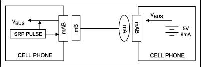
Figure 4. OTG Session Request Protocol (SRP).
Figure 4 shows a common OGT application: two cell phones connected together to exchange information. The right phone received the mini-A end of the cable, making it the A-Device and thus defaulting into the host role. The left phone is the B-Device, defaulting to peripheral. If there is no need to communicate over USB, the A-Device can power down the VBUS wire, which the B-Device can detect so that it too can enter a low-power state.
Now suppose that the user of the left phone presses a button to synchronize address books, or any other action that requires a USB session. The ‘SRP Pulse' block in the left phone pulses first the D+ wire, and then the VBUS wire to wake up the A-Device. (The A-Device can respond either to D+ or VBUS pulsing.) The A-Device then detects the pulse, causing it to switch on VBUS and start a session.
The SRP protocol is more complex than this simple illustration. The B-Device, for example, must first measure VBUS to ensure that a session is not in progress. It must also be able to differentiate between a classic PC or an OTG device at the other end of the cable. It does this by delivering measured amounts of current to the VBUS wire and noting the resulting voltage.
Once a session is underway, the devices may or may not use HNP.
OTG Transceiver
We are now ready to examine the requirements for an OTG transceiver, illustrated in Figure 5.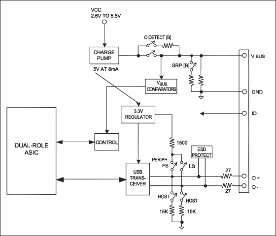
Figure 5. An OTG transceiver.
The Figure 5 system builds on the Figure 1example circuit. The ASIC block could also be a microprocessor or DSP with USB capability. Three additions make the transceiver OTG compatible:
- Switchable pull-up and pull-down resistors on D+/D- to allow peripheral or host functionality.
- Circuitry to monitor and supply 5V power on VBUS as an A-Device, and to monitor and pulse VBUS as a B-Device initiating SRP.
- An ID input pin, which is made available as an output to the ASIC.
Most of the added transceiver circuitry manages the VBUS pin, which now must also supply 5V power at 8mA as a host, and perform VBUS pulsing as a peripheral. Analog switches configure the transceiver for the various roles that it must play.
 電子發(fā)燒友App









評(píng)論