MAX1472是一款以晶振為基準的鎖相環(PLL) VHF/UHF發送器�,設計用于在300MHz至450MHz頻段發送OOK/ASK數據
2012-06-18 10:11:11 1152
1152 
求教高手,什么事32通道的紅外發射機����,課程設計做這個�,不理解這個概念
2014-12-19 22:16:57
MAX1472 - Evaluation Kit - Maxim Integrated Products
2022-11-04 17:22:44
EVAL KIT MAX1472
2023-03-22 19:18:46
BGTV4152型全固態電視發射機的原理是什么����?怎么維護BGTV4152型全固態電視發射機?
2021-06-03 06:06:32
干擾的情況下距離不超過5米�。
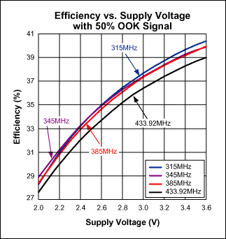
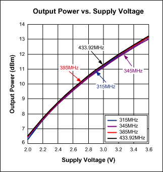
發射機功率在10dbm左右
左圖為有數據時的正常波形��,右圖為沒有數據時的雜波。
請問影響ASK Transparent serial mode的寄存器有哪些���,應該怎樣配置會使沒有收到正常數據時的雜波盡可能變少又不影響接收距離?
詳細配置在附件中���。
2018-05-14 02:20:25
自制簡易FM發射機
2013-11-11 13:52:22
:MAX1472、MAX7044�����、MAX1479和MAX7030/MAX7031/MAX7032)集成了獨特的功率放大器(PA)����,允許用戶在保證高效率的同時,合理控制RF輸出功率和發送器電流損耗,這種折中
2019-06-27 07:13:47
棒性�、以及與其它無線網絡共存的要求����,進一步凸顯了對發送功率嚴格控制的需求����。除了這些外部要求以外,精確的RF功率控制可以提高頻譜性能��,并且節省發射機功率放大器的成本和功耗��。為了調節發送功率���,通常在
2019-06-25 07:46:11
本文討論了移動通信向第三代(3G)標準的演化與發展����,給出了范圍廣泛的3G發射機關鍵技術與規范要求的概述�����。文章提供了頻分復用(FDD)寬帶碼分多址(WCDMA)系統發射機的設計和測得的性能數據,以Maxim現有的發射機IC進行展示和說明�����。
2021-06-02 06:47:56
�����,并具有造價低廉�、建設快捷、組網靈活之優點���。大功率短波通信 發射機通常是指輸出功率為5-20kW的短波通信發射機,采用此類發 射機進行超遠距離話音通信時���,可提高接收機輸入端信號的信噪比, 保證通話質可
2021-12-16 10:24:19
調頻發射機作為一種簡單的通信工具�,由于它不需要中轉站和地面交換機站支持�����,就可以進行有效的移動通信,因此深受人們的歡迎�����。目前它廣泛的用于生產���、保安����、野外工極管完成語音信號對載波信號的頻率調制�,并通過
2012-05-20 10:51:34
【作者】:孫軍;【來源】:《甘肅科技》2010年04期【摘要】:介紹了筆者在非洲幾內亞工作時所維護的我國上海東方明珠廠生產的20kW,PDM發射機的天調網絡的計算,此網絡在中波發射單頻單塔中是比較
2010-04-23 11:29:25
; 現貨MAX1472AKA &
2010-10-27 13:22:09
模擬光發射機按光波長分為兩大類: 1310nm 光發和 1550nm 光發�。由于 1310nm 光發是把射頻電視信號直接加在激光二極管上進行光強度調制的�����,稱為內調制光發: 1550nm 波長光發是把
2019-10-18 06:35:10
度增大,使CTB、cs0非線性指標劣化�,還會造成DFB激光器的過驅動��,導致光發射機輸出功率下降;輸入電平過小,光調制度降低��,則導致光發射機的載噪比指標不能滿足需求�����?����! ?.光纖連接器與法蘭盤均屬精密器件
2022-04-16 22:06:17
本文簡要介紹了3G基站發射機需要測試和分析的關鍵參數及其意義。
2021-06-01 07:06:49
單片機串行通信發射機資料
2012-08-20 11:00:10
如題���,直接上變頻發射機中���,采用Passive Mixer的話�����,PA輸出會有flo+3*fbb的spur��,不但造成ACP變差����,嚴重時還會影響發射機的EVM�����。請問站內大神們��,這個問題有什么好的解決方法呢?
2021-06-23 09:58:10
技術。LINC發射機技術的構架在1935年最先被Chirex提出,但是由于當時用模擬電路來實現三角函數及開方電路等比較復雜�����,導致LINC技術沒有受到足夠的重視���,直到1974年北美的Cox首次以LINC
2019-06-17 07:41:26
——從發射機的射頻輸出端口向發射機方向看過去的匹配情況��;和從天線輸入端口向天線方向看過去的匹配情況���。少了其中一項���,如用天饋線分析儀進行天饋線系統的匹配測量��,只能說完成了整個系統一半的測試����。在本文中����,討論了
2019-06-10 06:56:47
是4G(例如LTE-Advanced)技術���。這對于網絡運營商�、服務提供商和消費者來講是一個好消息。但采用MSR 多載波配置使得對MSR 基站發射機進行測試更具挑戰�。為確保MSR 基站的順利部署����,有必要通過一種快速�����、高效的途徑來應對測量挑戰����。
2019-07-19 07:59:21
`大功率發射機的水冷散熱解決方案調頻廣播發射機主要用于將調頻廣播電臺的語音和音樂節目以無線方式發射出去�。而傳調頻廣播發射機在運行的過程中會產生一定的熱量,溫度對發射機的性能影響比較大���,溫度過高或過低
2018-11-28 15:47:02
為滿足機載系統發射機需求,一種高功率發射組件的設計與實現—樊錫元
2021-01-08 06:43:42
如何使用Tektronix IConnect軟件為發射機建模����?
2021-05-08 06:04:25
小功率調幅發射機的原理是什么?如何去制作一種小功率調幅發射機呢�����?有哪些制作流程���?
2022-03-01 06:08:31
怎么提高發射機的ACLR����? 現在ACLR勉強達到-45dbc��,有時還差一點���,有哪些措施可以提高一下呢�?
2020-05-18 05:55:58
目前市場上具備FM發射功能的MP3備受消費者關注�����。這種功能看起來挺新奇�,也可以為MP3播放器增加賣點�,其實實現起來并不難。我們無線電愛好者也可以自己動手做一個小型的FM發射機�����。
2021-05-07 06:07:40
所示��。(2)設計要求①基本要求a. 工作頻率:fo=6~10MHz中任選一種頻率�����。b. 調制方式:AM、FM或FSK……任選一種��。c. 輸出功率:不大于20mW(在標準75Ω假負載上)���。d. 遙控對象:8個����,被控設備用LED分別代替���,LED發光表示工作���。e. 接收機距離發射機不小于10m。②
2022-01-25 07:31:58
怎么實現乒乓球發射機的設計?
2021-11-09 06:56:09
LTE-Advanced)技術��。這對于網絡運營商�、服務提供商和消費者來講是一個好消息�����。但采用MSR MC配置也是有代價的�����,即必須對MSR基站發射機進行測試。怎么應對多標準無線電基站發射機測試挑戰?這個問題急需解決��。
2019-08-08 08:12:56
怎么提高發射機的ACLR�����? 現在ACLR勉強達到-45dbc��,有時還差一點,有哪些措施可以提高一下呢?
2016-08-11 14:01:47
手持發射機遙控LED系統硬件主要有哪幾部分?手持發射機遙控LED系統軟件是由哪些模塊組成的?如何對手持發射機遙控LED系統的性能進行測試�?
2021-06-08 06:00:37
執行802.11克發射機測量應用指南1380-4
2019-08-20 14:39:51
[url=]無線電遙控發射機和接收機 ...[/url]
2015-07-25 18:32:46
�,放電管一端接同軸電纜芯線��,另一端接同軸電纜屏蔽線(屏蔽線通過網絡系統接地).通常發射天線下面都裝有放電球并有匹配網絡.匹配網絡還有一定的避雷設計��。因此����,為了有效地避雷,此避雷器應就近裝在發射機附近或發射機輸出直接裝避雷器再接到輸出電纜上,如在同軸電纜末端(上天線前)加裝一只避雷器����,避雷效果更好�。
2021-05-11 07:48:58
我現在是水聲發射機���,涉及到阻抗匹配�����,那么可以這么認為嗎��?發射機就相當于電源,換能器相當于負載�,發射機的輸出阻抗就相當于是電源內阻��,換能器的阻抗相當于負載阻抗��?要讓這兩者相等?順便提問一句��,一般都說從
2017-02-10 13:48:43
本人菜鳥 望論壇大神幫解決一下單片機的問題基于S51 調幅發射機的設計載波頻率 f=12MHz調制信號:1kHz正弦波穩定度 《=10的-4調幅系數 0.5輸出功率Pa》=30mW天線形式 拉桿天線
2014-07-01 20:05:50
雷達發射機是由哪幾部分組成的?怎么提高雷達發射機的探測距離��?雷達發射機的峰值功率和平均功率有什么關系����?
2021-06-26 07:08:34
~ 2.5GHz的頻率范圍和 佳的信號質量 SFE100測試發射機配有為大功率輸出而設計的放大器模塊,大輸出可達0.5W 內置碼流發生器和視音頻信號源 任意波形發生器功能 SFE100測試發射機簡便易操作
2019-12-25 15:05:33
要求模擬雷達發射機原理以及可以模擬通過改善某些參數來提高發射機性能�,
2013-04-27 08:27:14
寬帶直接變頻發射機電路功能與優勢是什么?請問如何設計并模擬寬帶直接變頻發射機����?
2021-04-13 06:32:29
激光發射機線性度控制電路
2019-09-29 10:22:31
我現在是水聲發射機,涉及到阻抗匹配���,那么可以這么認為嗎?發射機就相當于電源��,換能器相當于負載���,發射機的輸出阻抗就相當于是電源內阻�����,換能器的阻抗相當于負載阻抗?要讓這兩者相等�����? 順便提問一句���,一般都說
2020-07-17 08:11:32
雷達主要由天線��、發射機�����、接收機、信號處理機和終端設備等組成。 注:天線的方向性越強,天線波瓣寬度越窄,雷達測向的精度和分辨力就越高���。常用的雷達工作頻率范圍為220~35000MHz。雷達發射機的任務
2021-09-17 09:10:02
本篇博文是看完西安電子科技大學的魏青老師的課程所做的學習筆記,特此記錄����。文章目錄雷達發射機的任務和基本組成雷達發射機的主要質量指標脈沖調制器雷達發射機的任務和基本組成雷達發射機的任務任務:產生大功率
2021-09-14 08:08:56
MAX2606FM無線發射機電路
2007-06-11 09:52:29 170
170 to transmitOOK/ASK data in the 300MHz to 450MHz frequencyrange. The MAX1472 supports data rates up to100kbps, and adjustable output pow
2008-08-19 12:41:15 20
20 to transmitOOK/ASK data in the 300MHz to 450MHz frequencyrange. The MAX1472 supports data rates up to100kbps, and adjustable output pow
2008-08-19 12:46:08 38
38 描述 ADF7012是一款低功耗ASK/FSK/GFSK UHF發射機���,設計用于短程無線設備(SRD)��。輸出功率、輸出通道����、偏移頻率和調制類型均可通過4個32位寄存器編程設置�����。 利用小數N
2024-02-27 10:08:35
The MAX1472, MAX1479, and MAX7044 300MHz to 450MHz ASK transmitter ICs are used in applications
2010-11-08 18:04:00 1474
1474
發射機原理圖,是四管發射的.
2008-09-08 10:31:48 4425
4425 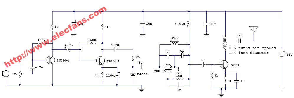
Designing Output-Matching Networks for the MAX1472 ASK Transmitter
The MAX1472 is a crystal-referenced phase-locked loop trans
2008-09-17 16:22:30 1255
1255 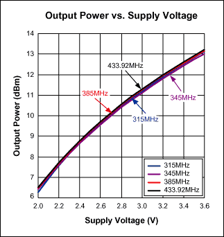
圖4為晶振式發射機電路�����。電
2008-10-18 09:02:17 3904
3904 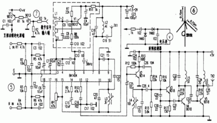
載波發射機原理圖
2009-03-19 10:56:50 717
717 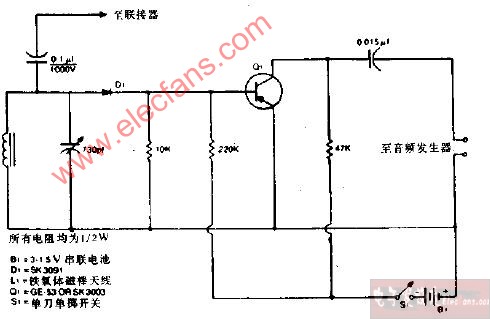
載波發射機原理圖
2009-03-25 08:37:49 1354
1354 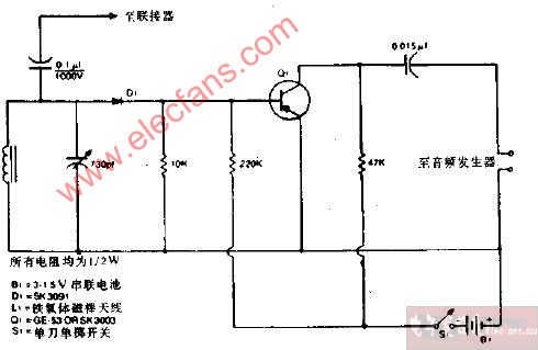
遙控發射機
該發
2009-10-06 11:47:18 711
711 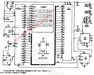
跟蹤發射機
該跟蹤發射機由以下四個不同的組件構
2009-10-10 11:48:55 607
607 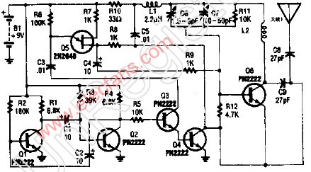
MAX1472 ASK發送器的輸出匹配網絡設計
MAX1472是以晶體為參考時鐘的鎖相環發送器�,設計用于發送30
2009-10-23 18:15:48 919
919 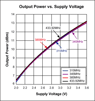
什么是光發射機�����? 光發射機由輸入接口�����、光源、驅動電路、監控電路、控制電路等構成,其核心是光源及驅動電路�����。在數字通信中�����,輸入電路將
2010-03-13 16:27:27 1330
1330 光發射機是網絡的核心設備��,維護人員應掌握其工作原理,對
一些故障可自行維修����,還應做好光發射機的備份��,以備應急之用。
2011-02-14 18:01:10 45
45 第一章 概論 第二章 真空管雷達發射機 第三章 固態雷達發射器技術 第四章 全固態雷達發射器設計與挑戰 第五章 脈沖調制器 第六章 發射機電源 第七章 發射機特種元件 .........................
2011-02-15 10:52:22 228
228 MAX7049高性能,單芯片���,超低功耗ASK / FSK UHF發射器在工業,科學,醫療(ISM)頻段在288MHz至945MHz的載波頻率經營
2011-07-08 11:26:50 2127
2127 
電子發燒友提供了電視發射機原理深入解析教材����,本PPT介紹了電視發射機原理圖,電視發射機工作原理��,數字電視發射機工作指標等信息��。
2011-12-09 11:01:33 0
0 Abstract: This application note illustrates the flexibility of the MAX7060 ASK/FSK transmitter.
2012-04-09 11:50:07 56
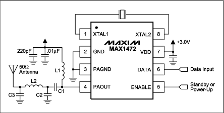
56 MAX1472在RF發射器應用中的典型工作電路圖
2012-09-27 17:03:00 2471
2471 
MAX1473 MAX1472發送器和接收器參考設計(RD)是一個獨立的評估平臺�,行使這兩種產品作為遠程無鑰匙進入(RKE)演示系統
2012-10-08 10:03:59 4973
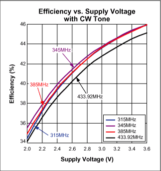
4973 美信MAX1472:300MHz至450MHz����、低功耗、基于晶振的ASK發送器
2014-03-01 11:05:22 1844
1844 
本實驗用雷達發射機可作為學員學習雷達發射機原理的教學儀器,理解雷達射頻信號的產生機理;可作為發射機頻率的測量��、發射機功率的測量��、發射機頻譜的測量�、饋線系統駐波比的測量��、雷達信號接收等實驗的配套儀器使用,提供射頻信號���。
2021-08-27 14:38:54 3075
3075 
ADF7011:高性能ISM頻段ASK/FSK/GFSK發射機IC數據表
2021-04-29 13:31:11 6
6 2022-11-18 23:45:15 0
0 本應用筆記給出了MAX1472的推薦輸出匹配網絡和輸出匹配網絡元件值���,MAX1472是一款300MHz至450MHz低功耗�����、基于晶體的ASK發送器。MAX1472的架構通過提供更大的調制深度���、更快
2023-01-13 16:19:15 489
489 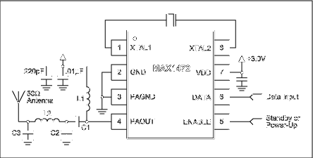
電子發燒友網為你提供Maxim(Maxim)MAX1472AKA相關產品參數、數據手冊�,更有MAX1472AKA的引腳圖��、接線圖、封裝手冊���、中文資料、英文資料����,MAX1472AKA真值表,MAX1472AKA管腳等資料����,希望可以幫助到廣大的電子工程師們���。
2023-01-14 18:45:45

電子發燒友網為你提供Maxim(Maxim)MAX1472AKA+T相關產品參數�����、數據手冊���,更有MAX1472AKA+T的引腳圖���、接線圖�、封裝手冊�����、中文資料�、英文資料��,MAX1472AKA+T真值表��,MAX1472AKA+T管腳等資料,希望可以幫助到廣大的電子工程師們���。
2023-02-05 19:08:30

本應用筆記顯示了小環路的典型阻抗值,并建議了這些阻抗的匹配網絡��。它證明了這些網絡在抑制發射頻率的諧波方面的有效性���。大多數用于這些應用的發送器IC�����,如Maxim MAX7044、MAX1472
2023-03-03 16:15:43 733
733 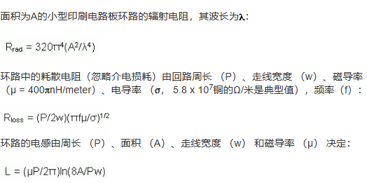
該F113是一種高性能,易于使用,單芯片ASK發射器在300至450MHz頻段的遠程無線應用集成電路�����。該發射機集成電路是一個真正的“數據輸入��,天線輸出”單片設備��。F113有三個強大的屬性:功率
2023-12-25 18:07:20 4
4


 電子發燒友App






評論