Abstract: Circuit including a step-up switching converter steals power from a parallel port, providing 5V at 8mA with efficiency as high as 94%.
The circuit of Figure 1 steals energy from a parallel port or from any limited-energy source. Such power-conversion applications usually require very high efficiency for making use of the energy available. A parallel-data port, for instance, provides as much as 2.6mA per data line at 2.4V. When the eight data lines are software-configured to FFHEX (all high), that condition yields an input power of 50mW. The system can then use the four bidirectional control-port lines and the five status-port inputs as an alternative means of communication through the PC's parallel port.
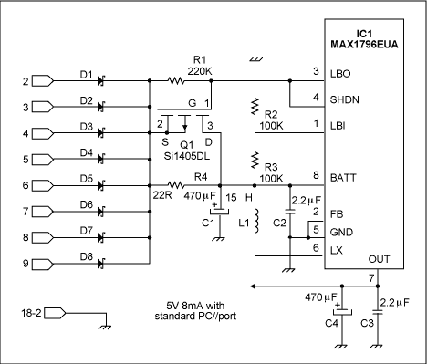
Figure 1.This circuit robs about 40mW (8mA at 5V) from an 8-bit data port whenever you program all bits high.
As shown in Figure 1, one Schottky diode per data line protects against possible errors. (Without diodes, the lines would short each other unless all were in the same state.) BAT54C devices contain two diodes per package, but exhibit a forward voltage drop of 0.3V. As an alternative, RB411D or ZHCS500 devices drop only 170mV but contain only one diode per SOT23 package.
An input voltage (logic high) of 2.4V leaves only about 2V for supplying the step-up circuit, and most such circuits (operating under low input voltage and low power) offer efficiencies no greater than 85%. IC1, however, by shunting the free-wheeling output diode with a synchronous p-channel MOSFET, provides an efficiency as high as 89% for the conditions of 2V input, 5V output, and 10mA output current. To gain a few more efficiency points, make a careful selection of the passive components.
The power inductor has a saturation current much higher than the operational current, so its ferrite loss is negligible. A good choice is the 15μH RCR110D (Sumida), which adds a low series resistance of 36mΩ maximum to a saturation current greater than 2.88A. Then, you can reduce loss in the input and output capacitors (C1 and C4) by selecting very low-ESR devices. Values of 470μF give them a comfortable reservoir capacity, and you can minimize the ESR by oversizing their voltage ratings. The 470μH ZLH by Rubycon, for example (despite being an affordable aluminium electrolytic), shows an ESR better than 45mΩ when rated at 25V.
For supplementary protection, the 22Ω resistor R4 limits input current to 100mA during startup. Note that R4 is shunted by Q1 as soon as enough voltage is detected by the 100K/100K divider (R2/R3). Even in an SC70 package, Q1 reduces the loss after startup to only 90μW. A 220kΩ gate resistor (R1) allows decent reaction times for an added loss of only 26μW.
Adding two 2.2μF capacitors (C2 and C3) near the MAX1796 eliminates high-frequency spikes, and X5R dielectric material allows 10V-rated devices to fit in an 0805 (TDK) package. All these measures add crucial points of efficiency, as shown in Figure 2.
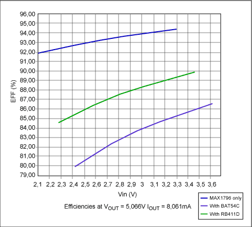
Figure 2. The efficiency of the Figure 1 circuit is highest when you remove the Schottky diodes (upper curve), and lowest for 0.3V (BAT54C) Schottkies. The middle curve is for 170mV (RB411D) Schottkies.
For the worst-case input voltage of 2.1V and without diodes, the efficiency of this circuit is about 92%. At 3.3V the efficiency reaches 94.4%, which is unusual for a low-power application such as this one. Using BAT54C protection diodes drops the efficiency to 80% at 2.4V, providing a typical output power of 40mW. If this is insufficient, you can increase the available power to 42.75mW by substituting the lower-voltage (RB411D) diodes.
A similar version of this article appeared in the December 9, 2004 issue of Electronic Design magazine.
The circuit of Figure 1 steals energy from a parallel port or from any limited-energy source. Such power-conversion applications usually require very high efficiency for making use of the energy available. A parallel-data port, for instance, provides as much as 2.6mA per data line at 2.4V. When the eight data lines are software-configured to FFHEX (all high), that condition yields an input power of 50mW. The system can then use the four bidirectional control-port lines and the five status-port inputs as an alternative means of communication through the PC's parallel port.

Figure 1.This circuit robs about 40mW (8mA at 5V) from an 8-bit data port whenever you program all bits high.
As shown in Figure 1, one Schottky diode per data line protects against possible errors. (Without diodes, the lines would short each other unless all were in the same state.) BAT54C devices contain two diodes per package, but exhibit a forward voltage drop of 0.3V. As an alternative, RB411D or ZHCS500 devices drop only 170mV but contain only one diode per SOT23 package.
An input voltage (logic high) of 2.4V leaves only about 2V for supplying the step-up circuit, and most such circuits (operating under low input voltage and low power) offer efficiencies no greater than 85%. IC1, however, by shunting the free-wheeling output diode with a synchronous p-channel MOSFET, provides an efficiency as high as 89% for the conditions of 2V input, 5V output, and 10mA output current. To gain a few more efficiency points, make a careful selection of the passive components.
The power inductor has a saturation current much higher than the operational current, so its ferrite loss is negligible. A good choice is the 15μH RCR110D (Sumida), which adds a low series resistance of 36mΩ maximum to a saturation current greater than 2.88A. Then, you can reduce loss in the input and output capacitors (C1 and C4) by selecting very low-ESR devices. Values of 470μF give them a comfortable reservoir capacity, and you can minimize the ESR by oversizing their voltage ratings. The 470μH ZLH by Rubycon, for example (despite being an affordable aluminium electrolytic), shows an ESR better than 45mΩ when rated at 25V.
For supplementary protection, the 22Ω resistor R4 limits input current to 100mA during startup. Note that R4 is shunted by Q1 as soon as enough voltage is detected by the 100K/100K divider (R2/R3). Even in an SC70 package, Q1 reduces the loss after startup to only 90μW. A 220kΩ gate resistor (R1) allows decent reaction times for an added loss of only 26μW.
Adding two 2.2μF capacitors (C2 and C3) near the MAX1796 eliminates high-frequency spikes, and X5R dielectric material allows 10V-rated devices to fit in an 0805 (TDK) package. All these measures add crucial points of efficiency, as shown in Figure 2.

Figure 2. The efficiency of the Figure 1 circuit is highest when you remove the Schottky diodes (upper curve), and lowest for 0.3V (BAT54C) Schottkies. The middle curve is for 170mV (RB411D) Schottkies.
For the worst-case input voltage of 2.1V and without diodes, the efficiency of this circuit is about 92%. At 3.3V the efficiency reaches 94.4%, which is unusual for a low-power application such as this one. Using BAT54C protection diodes drops the efficiency to 80% at 2.4V, providing a typical output power of 40mW. If this is insufficient, you can increase the available power to 42.75mW by substituting the lower-voltage (RB411D) diodes.
A similar version of this article appeared in the December 9, 2004 issue of Electronic Design magazine.
 電子發燒友App






評論