Saving Energy: Little Things Mean a Lot,節能:小事情意味著許多
Abstract: Consumers demand long battery life in their portable devices. Meanwhile for nonportable devices, increasing energy costs and the latest Energy Star? guidelines are focusing public awareness on wasted standby power. Thus, meeting green energy regulations and reducing standby power has become designers’ new mantra, especially when systems are active 24 hours a day. To meet the lower power-consumption levels, circuit designers know that the devil is in the details, with every single circuit required to justify its current budget. This article shows how Maxim chips can help system designers reduce the power budget of typical systems. The examples highlight just a few of the products in Maxim’s broad portfolio of ultra-low-current devices.
This article was also featured in Maxim's Engineering Journal, vol. 65 (PDF, 756kB).
Consumers demand long battery life in their portable devices, and rightfully so. Convenience is paramount, and that very concept permeates our society. We do not want to wait in lines, in traffic jams, etc., and further, we will often pay for that privilege. Hence, we have automatic teller machines dispensing cash 24/7; digital video recorders (DVRs) that allow us to time-shift our entertainment; mobile devices that let us communicate and entertain ourselves 24/7; and much more. "Little, light, fast, and easy" is today's consumer mantra. As equipment designers, we understand that our success requires meeting those expectations.
Making the equipment "greener" is a combination of integration, architecture, component selection, and function management to save every microamp in portable systems, and milliamps and more in line-powered systems. In portable systems, designers routinely count current in microamps. However, even that can be compromised when a single fingerprint on the circuit board might leak more current than a chip's standby current.
A popular song of the last five decades, "Little things mean a lot," teaches us how to design circuits for today's portable market. To paraphrase the song, with apologies to the song writers, "cause honestly, honey, they just cost" battery. We first think of the big items—a sleeping microprocessor, current-sipping displays, and flash memories—and then the rest of the circuitry. The devil is in the details, with every supporting circuit required to justify its current budget. Regulations vary by area, but typical goals for standby power are less than 0.5W to 3W, while typical goals for operating efficiencies of more than 80% are becoming commonplace.
As a consumer, reading our home utility power bill can be frightening. As an engineer, we can design circuits to help consumers reduce their power bills. For example, just look at the HDTV DVR receiver. A typical unit draws 120W and often has no standby mode. Running 24/7, it would cost $34.52 (U.S. dollars) a month to operate (based on the penalty power rate of $0.399 per kWh in northern California). This is just one appliance in our home, which emphasizes how the costs or potential savings can add up quickly. In a typical middle-class home there might be over 35 devices drawing power. Most, thankfully, probably have some form of standby power mode that reduces the power drain when the system is idle.
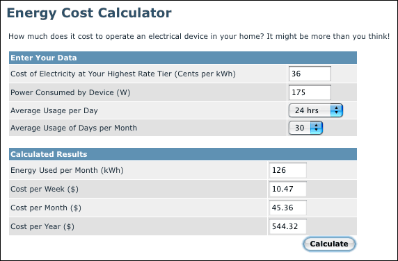
See als Energy Cost Calculator
Increasing energy costs are focusing consumer attention on the total cost of ownership. Power consumption is critical, and remember that, for every watt going into a room, it will cost about two watts for air conditioning to remove it. So for us engineers, exceeding green energy regulations is smart for our business and our planet.
An Elementary Working Machine
Today, we have motors and microprocessors working for us in our homes and workplaces. When a natural disaster occurs, we quickly remember how dependant our lifestyles are on electrical power.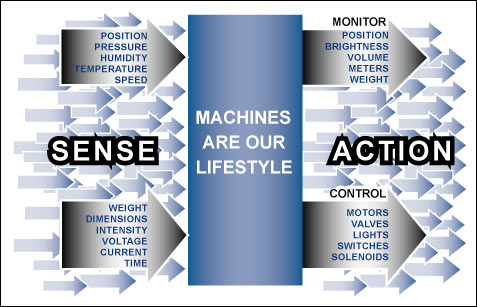
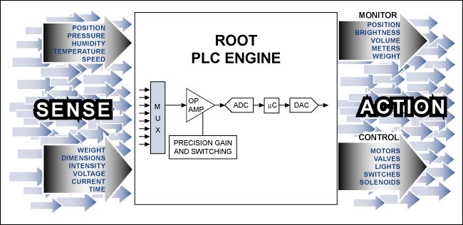
Figure 1. The shared characteristics of common machines dictate our lifestyles.
As we look at the block diagrams of machines, appliances, and entertainment devices, we see much in common. Figure 1 illustrates the simplest definition of a useful machine. We sense something and then initiate an action. This is really a definition of most work. For example, we sense the room temperature and turn on a heater or air-conditioning unit. We, or a machine, sense the light level and turn on the lights. Our lawn sprinkler controller senses time and turns on the water solenoid for a programmed period.
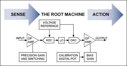
Figure 2. The concept of a simple useful machine is the basis for aPLC whose function is defined through a combination of software and silicon.
We start with the simplest of useful machines and then add features. Figure 2 is such a machine; it senses some parameter, uses a processor to evaluate the stimulus against a predetermined criterion, and starts an output action. (Yes, we could show a heater, air conditioner, or refrigerator with a bimetal mechanical switch, but we are building on this machine to make more sophisticated devices.) In fact, we are describing a programmable logic controller (PLC). In Figure 3 we start customizing the system to meet the customer's requirement.
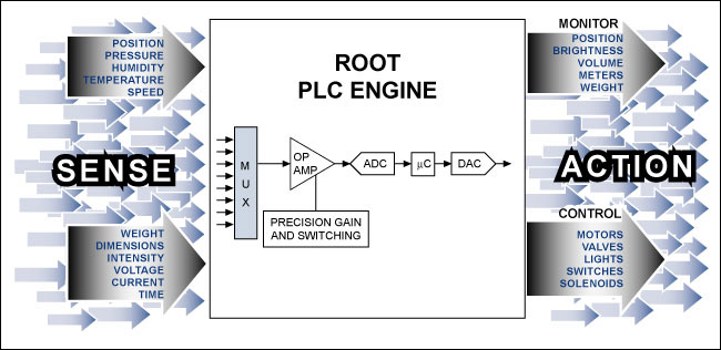
Figure 3. Highly integrated building-block ICs like those from Maxim can implement an elementary PLC.
To arrive at the system in Figure 3, we took the sensor inputs and action outputs and partitioned functions by the speed needed. Relatively slow-changing inputs and outputs can be multiplexed around one PLC engine. Multiple parallel PLCs may be required for sensors and actions, such as safety items, which require constant attention. Table 1 lists possible components for this root PLC engine. We can multiplex the sensors and condition the signals by switching gain and offset in the initial op amp. In any large-volume consumer device this amplifier must be inexpensive. A low-power CMOS op amp such as the MAX9915 can deliver the necessary precision for the control loop. The system dictates which of several amplifier configurations will be used.
Table 1. Typical Low-Current Maxim ICs Used for the Root PLC
| Part | Description | Current Consumption |
| MAX1108/MAX1109 | 8-bit ADC, dual-channel, 50ksps | Operates on < 130μA;standby < 0.5μA |
| MAX6029 | Series voltage reference, 0.15% initial accuracy | Operates on 5.25μA (max) |
| MAX5380/ MAX5381/MAX5382 | 8-bit DAC, 2-wire serial interface, 5-pin SOT23 package | Operates on 230μA; standby 1μA |
| MAX9915 | Op amp, 1MHz unity-gain BW, rail to rail | Operates on 20μA; standby 0.001μA |
| MAX5490/ MAX5491/MAX5492 | Precision-matched resistor-divider, 0.025% tolerance | Operates on ZERO A; standby ZERO A |
| MAX5426 | Digitally-programmable resistor network for instrumentation amps | Operates on 90μA |
| MAX5430 | Digitally-programmable precision voltage-divider for programmable-gain amps | Operates on 6μA |
| MAX308, MAX4581 | 8-to-1 analog multiplexer | Operates on < 17μA |
| MAX5128 | Digital potentiometer, nonvolatile | Standby 0.5μA |
| DS80C320/DS80C323 | Microcontrollers, 80C31/80C32 compatible, fast for power saving | Stop mode: 50μA with bandgap on; 1μA with bandgap off |
There are several possible amplifier configurations:
- The input amplifier stage may consist of a MAX9915 op amp and the MAX5490/MAX5492 precision-matched resistor-dividers, which are matched to within 0.025%. This combination leverages a relatively modest op amp, yet delivers precise gain and an excellent temperature coefficient.
- We could add three op amps and a MAX5426 digitally-programmable resistor network to make a differential-input instrumentation amplifier.
- If a programmable-gain amplifier with digitally programmable precision gains of 1, 2, 4, and 8 is needed, then we combine the MAX5430 precision voltage-divider with an op amp.
- Alternatively, the gain, bias, and offset could be set with digital potentiometers such as the MAX5128. The MAX5128 even integrates a nonvolatile memory so you can set and retain any gain setting. Upon power-up, the pot assumes the previous value—a potent tool for calibrating levels and offsets.
The DS80C320/DS80C323 are fast 8051-compatible microcontrollers. These high-integration controllers include four 8-bit I/O ports, two full-duplex hardware serial ports, timer/counters, a watchdog timer, and scratchpad RAM. By allowing more sleep cycles, their high-speed architecture uses less power for equivalent work.
The output of the microprocessor is converted to an analog signal by the MAX5380/MAX5381/MAX5382 8-bit DACs that use a two-wire serial interface to squeeze the circuit into a space-saving 5-pin SOT23 package. The DACs also integrate an output buffer amplifier to further reduce component count and board space.
Growing the Root PLC for More Complex Devices
By detailing the most elementary PLC engine, it is clear how features can be added to match the application. Everyone wants more convenience, which usually means more features/specialized functions. This is the "feature creep" that circuit designers hate. Sales wants many features included, but the retail price cannot increase. Designers thus must be clever enough to keep costs in check. Many of Maxim's highly integrated solutions help designers meet their application goals by reducing current consumption, size, and cost.We are all obligated to conserve energy, and Maxim takes that obligation seriously. The Company uses its R&D expertise to design and support a broad line of power-conserving and energy-efficient products. Only a few Maxim devices were highlighted in this article. These devices are just part of Maxim's broad portfolio of ultra-low-current products.
Energy Star is a registered trademark of the U.S. Environmental Protection Agency.
 電子發燒友App





評論