Abstract: This application note discusses "Charlieplexing" -- a pin-count reducing multiplex technique used by the MAX6950, MAX6951, MAX6954, MAX6955, MAX6958, and MAX6959 LED display drivers.
This application note discusses how to "Charlieplex" a display driver circuit to reduce pin-count. This unusual multiplex technique is used by the MAX6950, MAX6951, MAX6954, MAX6955, MAX6958, and MAX6959 LED display drivers. Charlieplexing reduces driver pin-count by using some pins alternately as cathode and anode drivers. This differs from the standard LED multiplex connection, which uses separate driver pins for anodes and cathodes.
The standard connection for multiplexing common cathode (CC) LED digits uses a separate pin for each digit's CC connection, while the anode segment connections are communed across all the digits. Similarly, the standard connection for multiplexing common anode (CA) LED digits uses a separate pin for each digit's CA connection, while the cathode segment connections are communed across all the digits. The number of connections required can be calculated as being 1 for every digit used, plus 1 for every segment within a digit. Therefore an 8-digit, 8-segment multiplex driver typified by the MAX7219 and MAX7221 CC drivers uses 8 cathode drive pins and 8 anode drive pins, 16 drive outputs in total (Figure 1).

For Larger Image
Figure 1. The MAX7219 and MAX7221 use standard connections - 16 pins to drive 8 digits.
A more pin-efficient scheme relies on the fact that during the multiplex operation, only one CC or CA digit drive output is actually in use. The other digit drives are high-impedance, ensuring that no drive current flows into these undriven digits. By making the LED drive pins alternate duty between driving digits and segments, n drive pins can be used to drive n digits each with n-1 segments. Charlie Allen originally championed this technique internally at Maxim, and so the shorthand name "Charlieplexing" came into use to distinguish reduced pin count multiplexing from the traditional method. The first Maxim product to use Charlieplexing is the Maxim MAX6951 LED driver, which drives 8 numeric digits with only 9 pins (Figure 2).

For Larger Image
Figure 2. The MAX6951 uses Charlieplexing - only 9 pins to drive 8 digits.
To understand how Charlieplexing works, first examine the pin connections shown in Table 1. There is one row per multiplexed digit, and each row contains 9 columns. For each digit, one column corresponds to the CC digit drive, and the remaining 8 columns correspond to the 8 anode (segment) drives.
Table 1. The MAX6951 Driver to LED Display Connections
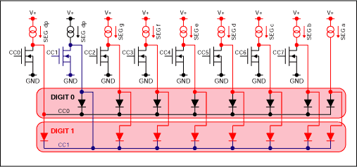
The diagrams in Figures 3 and 4 show the current flow in the MAX6951 during the multiplex cycles for digit and digit 1 respectively. The circuit shows the MAX6951's 8 internal power NMOS devices used for cathode drives CC0 through CC7, and the 9 segment drive current sources. The external LED digit connections for digits 2 through 7 are omitted for simplicity.
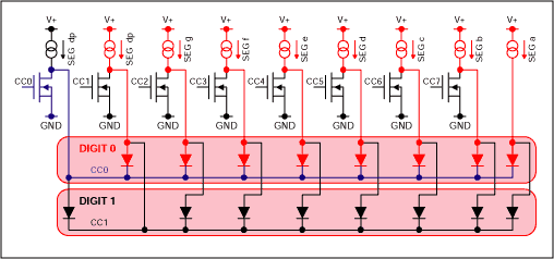
Figure 3. The MAX6951 current flows during digit 0 multiple cycle.
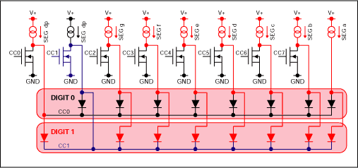
Figure 4. The MAX6951 current flows during digit 1 multiple cycle.
Looking at Figure 3 first for the digit 0 drive case, cathode drive CC0 is on, pulling digit 0's 8 common cathodes hard to GND. 8 of the 9 segment drive current sources are also on, driving current into digit 0's 8 anodes. Digit 0 can therefore light all 8 of its LEDs. Now consider digit 1. The common cathode connection, CC1, is shared with digit 0's SEG dp connection, which is driven well above GND as a current source. The anode connections for digit 1 are also either tied to a similar SEG connection, or tied to GND in the case of the first (leftmost) segment. The first segment of digit 1 is clearly reversed, so cannot light. The other digit 1 segments are effectively connected between anodes of the lit or unlit segments of digit 0. An unlit segment's current source is very high impedance, and will not supply current. The voltage difference between any 2 lit segments of an LED digit will be a small positive or negative voltage, reflecting the matching between the digit's individual LEDs. Unless the mismatch is much higher than 1V, digit 1's LEDs won't have a high enough voltage to even start to turn on. A realistic maximum mismatch is a few hundred millivolts.
Figure 4 shows the case for digit 1 being driven. This time, digit 0's segments are either reverse biased or biased by a random amount inadequate to light the segments.
Charlieplexing puts LED segments in reverse bias during a portion of the multiplexing time. The maximum applied reverse bias voltage is the value of the supply voltage, V+, and occurs when an LED is reverse biased between another digit's turned-on cathode drive, and a current source which is driving an open circuit (such as a dead or missing LED). It is therefore important to ensure that the LEDs chosen are rated to withstand a reverse bias equal to the maximum supply voltage applied to the driver.
For further reference, other technical discussions of pin-reduced LED drive techniques include Microchip's TB029 application note (www.microchip.com) and Don Lancaster's August 2001 Tech Musings (www.tinaja.com).
This application note discusses how to "Charlieplex" a display driver circuit to reduce pin-count. This unusual multiplex technique is used by the MAX6950, MAX6951, MAX6954, MAX6955, MAX6958, and MAX6959 LED display drivers. Charlieplexing reduces driver pin-count by using some pins alternately as cathode and anode drivers. This differs from the standard LED multiplex connection, which uses separate driver pins for anodes and cathodes.
The standard connection for multiplexing common cathode (CC) LED digits uses a separate pin for each digit's CC connection, while the anode segment connections are communed across all the digits. Similarly, the standard connection for multiplexing common anode (CA) LED digits uses a separate pin for each digit's CA connection, while the cathode segment connections are communed across all the digits. The number of connections required can be calculated as being 1 for every digit used, plus 1 for every segment within a digit. Therefore an 8-digit, 8-segment multiplex driver typified by the MAX7219 and MAX7221 CC drivers uses 8 cathode drive pins and 8 anode drive pins, 16 drive outputs in total (Figure 1).

For Larger Image
Figure 1. The MAX7219 and MAX7221 use standard connections - 16 pins to drive 8 digits.
A more pin-efficient scheme relies on the fact that during the multiplex operation, only one CC or CA digit drive output is actually in use. The other digit drives are high-impedance, ensuring that no drive current flows into these undriven digits. By making the LED drive pins alternate duty between driving digits and segments, n drive pins can be used to drive n digits each with n-1 segments. Charlie Allen originally championed this technique internally at Maxim, and so the shorthand name "Charlieplexing" came into use to distinguish reduced pin count multiplexing from the traditional method. The first Maxim product to use Charlieplexing is the Maxim MAX6951 LED driver, which drives 8 numeric digits with only 9 pins (Figure 2).

For Larger Image
Figure 2. The MAX6951 uses Charlieplexing - only 9 pins to drive 8 digits.
To understand how Charlieplexing works, first examine the pin connections shown in Table 1. There is one row per multiplexed digit, and each row contains 9 columns. For each digit, one column corresponds to the CC digit drive, and the remaining 8 columns correspond to the 8 anode (segment) drives.
Table 1. The MAX6951 Driver to LED Display Connections
| ? |
Pin 6 |
Pin 5 |
Pin 4 |
Pin 3 |
Pin 14 |
Pin 13 |
Pin 12 |
Pin 11
|
Pin 10 |
|
|
|
|
|
|
|
|
|
|
|
|
|
|
|
|
|
|
|
|
|
|
|
|
|
|
|
|
|
|
|
|
|
|
|
|
|
|
|
|
|
|
|
|
|
|
|
|
|
|
|
|
|
|
|
|
|
|
|
|
|
|
|
|
|
|
|
|
|
|
SEG f
|
|
|
|
|
|
|
|
|
|
|
|
|
|
|
|
|
|
The diagrams in Figures 3 and 4 show the current flow in the MAX6951 during the multiplex cycles for digit and digit 1 respectively. The circuit shows the MAX6951's 8 internal power NMOS devices used for cathode drives CC0 through CC7, and the 9 segment drive current sources. The external LED digit connections for digits 2 through 7 are omitted for simplicity.

Figure 3. The MAX6951 current flows during digit 0 multiple cycle.

Figure 4. The MAX6951 current flows during digit 1 multiple cycle.
Looking at Figure 3 first for the digit 0 drive case, cathode drive CC0 is on, pulling digit 0's 8 common cathodes hard to GND. 8 of the 9 segment drive current sources are also on, driving current into digit 0's 8 anodes. Digit 0 can therefore light all 8 of its LEDs. Now consider digit 1. The common cathode connection, CC1, is shared with digit 0's SEG dp connection, which is driven well above GND as a current source. The anode connections for digit 1 are also either tied to a similar SEG connection, or tied to GND in the case of the first (leftmost) segment. The first segment of digit 1 is clearly reversed, so cannot light. The other digit 1 segments are effectively connected between anodes of the lit or unlit segments of digit 0. An unlit segment's current source is very high impedance, and will not supply current. The voltage difference between any 2 lit segments of an LED digit will be a small positive or negative voltage, reflecting the matching between the digit's individual LEDs. Unless the mismatch is much higher than 1V, digit 1's LEDs won't have a high enough voltage to even start to turn on. A realistic maximum mismatch is a few hundred millivolts.
Figure 4 shows the case for digit 1 being driven. This time, digit 0's segments are either reverse biased or biased by a random amount inadequate to light the segments.
Charlieplexing puts LED segments in reverse bias during a portion of the multiplexing time. The maximum applied reverse bias voltage is the value of the supply voltage, V+, and occurs when an LED is reverse biased between another digit's turned-on cathode drive, and a current source which is driving an open circuit (such as a dead or missing LED). It is therefore important to ensure that the LEDs chosen are rated to withstand a reverse bias equal to the maximum supply voltage applied to the driver.
For further reference, other technical discussions of pin-reduced LED drive techniques include Microchip's TB029 application note (www.microchip.com) and Don Lancaster's August 2001 Tech Musings (www.tinaja.com).
 電子發燒友App










評論