Continuous-Wave Doppler (CWD) Design Challenges in Compact Ultrasound-Imaging Equipment
Abstract: Recent advances in highly integrated, low-power bipolar amplifiers and continuous-wave Doppler (CWD) mixer/beamformer chips now allow designers to achieve high-end CWD performance for the next generation of compact ultrasound-imaging equipment.
A version of this application note was published in Chinese in EEPW magazine in February, 2009.
One of the most demanding clinical diagnostic tools employed in ultrasound systems is continuous-wave Doppler (CWD). Unfortunately, design tradeoffs required to minimize space and cost have resulted in CWD receiver implementations with less than optimal sensitivity. By analyzing why current-generation CWD receivers have limited performance, designers can leverage recent advances in integration that yielded highly integrated, low-power bipolar amplifiers and CWD mixer/beamformer chips. These next-generation circuits allow new CWD solutions to provide uncompromised diagnostic performance.
CWD Basics
In a typical phased-array CWD implementation, the 64 to 128 available ultrasound transducer elements are split into approximately equal halves about the center of the transducer aperture. Half of the elements are used as transmitters to produce a focused acoustic CWD transmit beam, and the other half as receivers to produce a focused receive beam. The signals applied to the transmit elements are square waves at the Doppler frequency of interest, typically 1.0MHz to 7.5MHz. The transmit beam is focused by properly phasing the signals applied to the transmit elements. In a similar way, the CWD received signals are focused by phasing and summing the signals from each receive element.
The resultant "beamformed" CWD received signal is a combination of strong signals from stationary tissue, commonly referred to as clutter, and the much weaker Doppler signals from moving blood. The typical clutter signal on the input of an individual phased-array receive channel can be as large as 200mVP-P, whereas the noise floor of the receiver referred to input can be as low as 1nV/ . This suggests that a per-channel SNR of approximately 157dBc/Hz is required for optimal receiver performance.
For a typical hypothetical CWD receiver with 64 channels, it should be noted that the SNR requirements are extreme. The noise from each of the receive channels is not coherent, and, as a result, the noise floor of the summed 64-channel, beamformed signal will be approximately 18dB above the noise floor of an individual channel. The CWD signal on each channel, however, is coherent and the beamformed CWD signal should be approximately 36dB larger than the CWD signal on an individual channel. This "summing gain" effect results in a required beamformed SNR approximately 18dB higher than an individual channel, or about 175dBc/Hz! To make matters even more difficult, low-velocity Doppler signals of interest can be within 1kHz or less of the clutter signal. One can easily appreciate why this ultrasound modality is so challenging to implement effectively.
Delay-Line-Based CWD Beamforming
Current compact ultrasound systems have typically implemented CWD using an analog delay-line receiver (Figure 1). Input signals from the ultrasound receive elements are buffered and amplified by approximately 20dB using LNAs. The outputs of these LNAs are converted to currents, which are then beamformed at the incoming RF frequency using a combination of crosspoint switches and analog delay lines.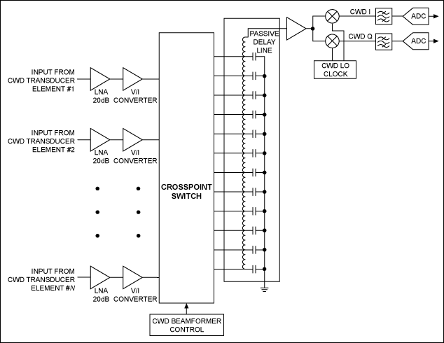
Figure 1. A simplified diagram of a CWD delay-line-based receiver.
This architecture is relatively easy to implement in a compact system since it relies on easy-to-integrate voltage-to-current converters, analog switches, a few passive delay lines, and a single I/Q mixer pair. The required delay for each receiver is achieved by programming the crosspoint switches to sum and route current signals through the appropriate taps in the delay line.
The beamformed RF CWD signal is then mixed to baseband I and Q audio frequency signals, so the I and Q signals can be bandpass filtered and then converted to a digital format using high-resolution audio ADCs for digital spectral processing. The RF-to-baseband mixing process is generally the SNR bottleneck in this receiver lineup, and is where significant CWD performance degradation occurs. The I/Q RF mixers for the beamformed signal require a dynamic range of approximately 175dBc/Hz at a 1kHz offset in this 64-channel example.
Mixers with such a performance capability are extremely difficult to find or design. In addition, local-oscillator drive signals must have extremely low jitter performance. Unfortunately, no readily available logic family has performance near this level. Although delay-line CWD beamformer implementations meet the minimal needs of compact ultrasound systems, the performance limitations caused by these issues can be significant.
Mixer-Based CWD Beamforming
A higher performance approach to craft a CWD system employs a CWD mixer/beamformer, shown in simplified form in Figure 2. In this implementation, an I/Q mixer is provided for each channel, and the beamforming summation occurs at baseband instead of at RF. The LO phase for each I/Q mixer in this implementation is programmable to one of n = 8 to 16 phases. Changing the phase of the LO changes the phase of the received signal, and beamforming is achieved.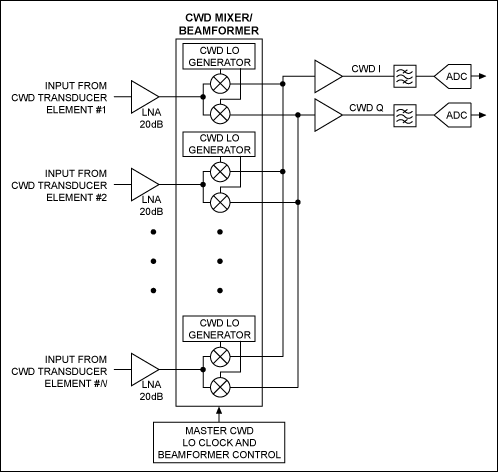
Figure 2. Low-power bipolar LNAs and a CWD mixer/beamformer can implement a simple, high-performance CWD receiver.
Because the mixers are implemented on a per-channel basis, the SNR requirements for each mixer can be relaxed to 157dBc/Hz at a 1kHz offset. This SNR is still very demanding, but is achievable using bipolar mixers and standard logic families. Since the mixer outputs are currents and passively summed at audio baseband frequencies, the required beamformed CWD SNR can be achieved.
Mixer-Based CWD Beamforming Solutions
In the past, implementation of this superior type of CWD beamformer architecture was not practical for a large number of ultrasound systems because of inadequate integration. This is no longer the case. For less power-sensitive applications requiring uncompromised CWD and imaging performance, there are integrated bipolar octal VGAs with programmable CWD mixer/beamformer channels. The MAX2038 VGA is shown in the receiver lineup in Figure 3.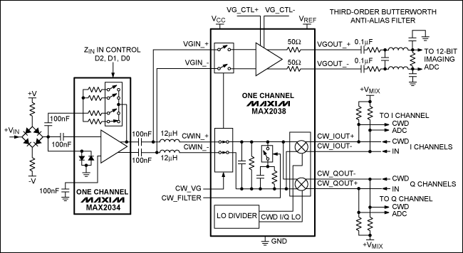
Figure 3. This simplified single-channel ultrasound receiver features the MAX2038 and MAX2034. The MAX2038 integrates eight VGA and CWD I/Q mixer/beamformer channels, and the MAX2034 integrates four LNA channels.
For applications where power and space are at a higher premium, there are newer, more highly integrated and lower power solutions like the MAX2078 in Figure 4. This chip contains fully integrated octal receivers incorporating LNAs, VGAs, anti-aliasing filters, and programmable CWD mixer/beamformer channels in a single bipolar IC. Now a wider variety of ultrasound systems can achieve excellent CWD performance without the previous limitations associated with delay-line CWD architectures.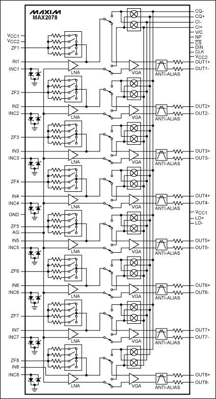
Figure 4. The MAX2078 ultra-low-power, octal ultrasound receiver with CWD beamformer integrates eight high-performance, low-power, ultrasound receive channels, which include an LNA, VGA, anti-aliasing filter, and fully programmable I/Q mixer/beamformer.
It should be noted that an additional potential problem in the implementation of any CWD receiver is the SNR performance of the LNA amplifiers. Many ultrasound system designers have chosen CMOS LNAs to reduce size and power. While these devices may seem appropriate for the application, they can limit CWD performance. This is especially true of amplifiers fabricated in CMOS geometries less than 0.35μm. Circuits implemented in those smaller process nodes typically have higher 1/f noise, and 1/f noise can cause low-frequency modulation of the LNA gain—a very undesirable effect.
A large RF CWD clutter signal passing through an LNA of this type will produce significant low-frequency-modulated noise skirts that can corrupt SNR performance and reduce CWD sensitivity. As a result, low-power bipolar LNAs like the 4-channel MAX2034 are generally preferable for this type of application.
Agilent is a trademark of Agilent Technologies, Inc.
Tektronix is a registered trademark of Tektronix, Inc.
 電子發燒友App









評論